 Animal Cage Camera (A3034)
© 2018-2024 Kevan Hashemi,
Open Source Instruments Inc.© 2018 Michael Collins, Open Source Instruments Inc.
| Spring-18 | Spring-19 | Summer-19 | Fall-19 | |
| Winter-19 | Spring-20 | Summer-21 | Spring-22 | |
| Winter-22 | Spring-23 | Fall-23 | Winter-23 | |
| Spring-24 |
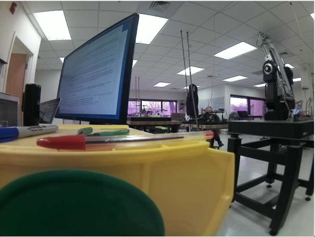
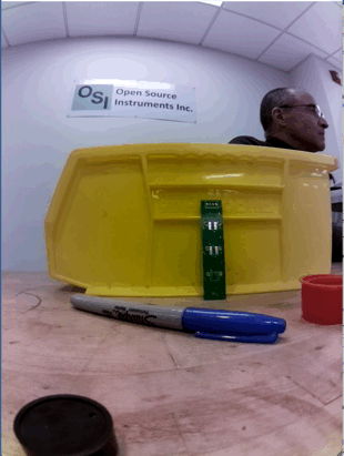
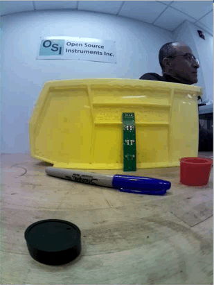
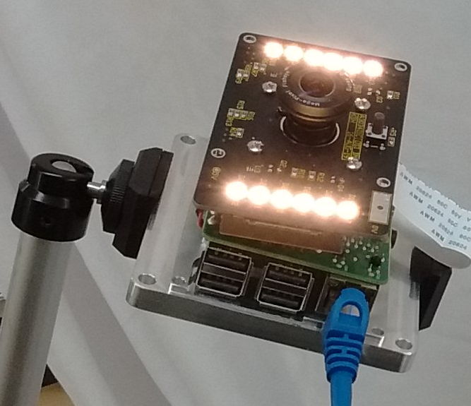
[28-MAR-24] The Animal Cage Camera (A3034, ACC) operates with the Videoarchiver Tool to provide high-definition, compressed video that is synchronous with biometric signals recorded by our subcutaneous transmitters (SCTs). The ACC is a black-anodized aluminum cuboid that sits securely on a flat surface for horizontal viewing, mounts in a mobile phone stand for elevated viewing, and fits behind the cages of a an individually ventilated cage (IVC) rack where we can zip-tie it to the ventilation pipes.
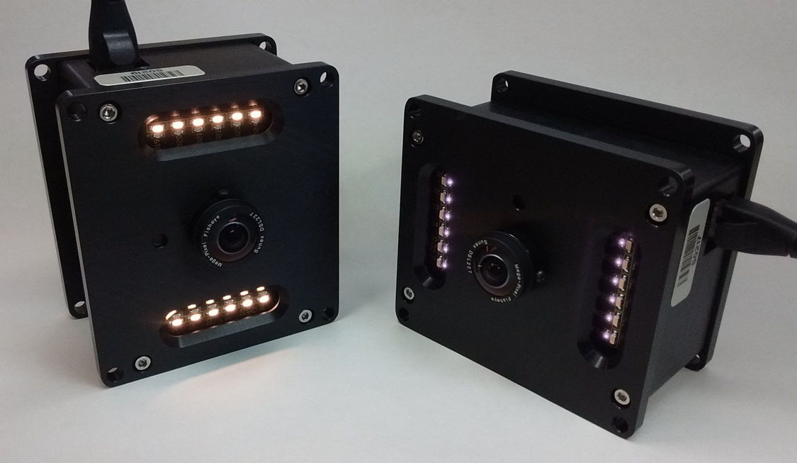
The ACC provides independent, variable-intensity, white and infrared light-emitting diodes (LEDs) to illuminate their own field of view. With the help of a day-night program running with the Videoarchiver, we can alternate between white and infrared light do simulate night and day. Its lens has no infrared blocking filter. The lens provides gray-scale images in infrared light, and balanced, crisp, full-color images in the light of its white LEDs. With the help of the Videoarchiver's scheduling component, we can alternate white and infrared illumination during day and night hours, and so obtain full-color images during the day, and gray-scale images at night.
The ACC offers three significant advantages over commercially-available webcams. Its video recordings are synchronous to ±100 ms with respect to a central data acquisition computer's clock. We can place the camera right up against an animal cage wall and view the entire cage without seeing its own infrared or white LEDs reflected in the wall. We can use the ACC recordings directly with the Neuroplayer to navigate through telemetry recordings.
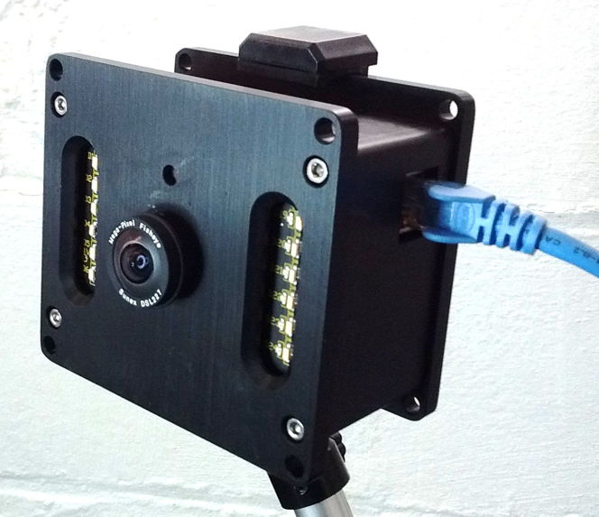
Power and communication are provided to the ACC by a single Power-over-Ethernet (PoE) cable. A single PoE switch with twelve or more ports allows us to connect ten ACCs, a LWDAQ Driver, and a data acquisition computer to the same local network. With such a network, we can record biometric signals from dozens of animals, along with synchronous video of those same animals from ten different points of view. The A3034C's wide-angle DSL227 lens and IMX219 full-color image sensor together provide a 148-degree diagonal field of view. When delivered by OSI, the center of the A3034C's depth of field is at range 40 cm, which provides sharp images of objects from ranges 20 cm to infinity. We say the focal range of the camera is 40 cm, and the depth of field is 20 cm to infinity. If we want to view objects 10 cm away, we adjust the lens-fastening screws so they allow the lens to rotate smoothly but with resistance, so the lens will remain where it is when we let go of it. WE rotate the lens counter-clockwise to reduce the focal range. We do not tighten the screws after we adjust the focal range, because tightening the screws moves the lens and changes the focal range. The A3034C offers two video output formats. The A3034B-HR format is 820 pixels wide and 616 pixels high (820 × 616) at twenty frames per second (20 fps) with standard-quality output. The A3034B-LR format is 410 × 308 at 30 fps with high-quality output. The video files produced by both formats take up roughly 5 GByte/day when viewing animals in a cage with infra-red illumination at night. The low-resolution format provides sharper images of fast-moving animals, while the high-resolution format provides sharper images of small, slow-moving animals.

The ACC is intended for operation in clusters of up to ten cameras, all controlled by one Videoarchiver Tool. The Videoarchiver provides live display of camera video on the computer screen for use when you set up your camera. The delay between movement in the camera field of view and its appearance in the live display should be less than fifty milliseconds. To record video to disk, we stop the live display, and instead initiate segmentation and compression of video on the camera itself, which the Videoarchiver downloads and concatenates into time-stamped video files that are synchronous with the local data acquisition computer clock. While recording to disk, we can view the compressed video as it arrives at the data acquisition computer, but this view will be delayed by several seconds. This delay does not represent a lack of synchronization with the local clock.
| Version | Features | Image Sensor | Lens | FOV | Video | Markings |
|---|---|---|---|---|---|---|
| A3034B1-A | Raspberry Pi 3B+, raspivid interface. Requires unshielded cable to Faraday enclosure |
IMX219 | DSL227 | 148° | 820 × 616, 20 fps, H264, crf=23 |
None |
| A3034C1-A | Raspberry Pi 3B+, raspivid interface. | IMX219 | DSL227 | 148° | 820 × 616, 20 fps, H264, crf=23 |
None |
| A3034C2-A | Raspberry Pi 3B+, libcamera interface. | IMX219 | DSL227 | 148° | 820 × 616, 20 fps, H264, crf=27 |
Orange Dot |
| A3034C2-B | Raspberry Pi 3B+, libcamera interface. | IMX219 | DSL215 | 180° | 820 × 616, 20 fps, H264, crf=27 |
Orange Dot |
The video produced by the A3034 is compressed with the H264 algorithm using crf=23 (constant rate factor set to twenty-three), which provides well-defined images of moving animals. A ten-minute, 820 × 616, 20 fps video of moving animals will occupy roughly 30 MBytes on disk. The compressed video contains key frames at the start of every whole second marked by the data acquisition computer's clock. These key frames allow the Neuroplayer to jump quickly and accurately to any whole-second boundary within the video recording, and at the same time display the simultaneous biometric signals with synchronization accuracy ±50 ms.
The ACC is designed to be quiet and reliable. Its power converters are long-live, encapsulated devices run at frequencies well above the ultra-sonic frequencies mice can hear. The ACC contains no fan. It dissipates the heat generated by video compression by means of conduction, radiation, and un-forced convection alone. During video recording, its case will be 15°C warmer than ambient. The PoE switch that supplies power and communication for the cameras should be quiet also. We recommend a switch such as the GS116PP, which has no fan and provides more than 12 W electrical power for each of ten cameras.
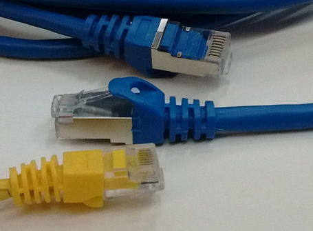
Each ACC requires only one cable for power and communication, but we must use the right kind of cables. For gigabit PoE connections, we must use Cat-5E or higher network cables. The A3034B (cameras S0205-S0217) requires that we use unshielded cables from the switch to the Faraday enclosure because of a weakness in its design. The A3034C and later versions work fine with either shielded or unshielded cables from the switch to the Faraday enclosure. Our subcutaneous transmitters systems almost always operate within some kind of Faraday enclosure, such as the FE3AS). These enclosures are designed to be electrically quiet, both at the low frequencies of biometric signals, and the much higher frequencies of radio-frequency interference. When we install a camera inside such an enclosure, we rely upon the aluminum case of the camera to keep its own electrical noise contained, but we must in addition use a shielded network cable between the camera and the Faraday enclosure wall. Thus, we always use a short, shielded network cable to connect the feedthrough to the camera inside the enclosure. If we do not use a shielded cable inside the enclosure, we introduce mains hum and radio-frequency interference into the enclosure volume.
Do Not Over-Tighten Lens Screws: Lens screws are for generating friction only. Over-tightening spoils the camera focus.
Warning: Do not plug the camera into the front-panel sockets of a LWDAQ Driver.
[07-DEC-23] In order to communicate with your ACC when you first receive it, you must configure your computer's wired Ethernet interface to communicate on subnet 10.0.0.x. You assign your computer an IP address like 10.0.0.2, and you give it "subnet mask" 255.255.255.0. On MacOS, create a new location with the Locations Manager, which is accessible through the Networks icon in System Settings. Select your wired Ethernet connection and configure it using the graphical user interface of the Locations Manager. We have specific instructions for Windows 7 and Windows 10. On Linux, you edit file /etc/dhcpcd.conf to configure your wired ethernet interface, which may be called eth0, or may be called something long and cryptic if you have "predictable interface names" on your version of Linux.
The diagram below shows how four ACCs, a data acquisition computer, and a LWDAQ Driver (A2071E) connect to the same local network provided by a single PoE switch. Two cameras are set up outside a Faraday enclosure, and two more are set up inside the the Faraday enclosure. An Octal Data Receiver A3027E is connected to the LWDAQ Driver and to two Loop Antennas (A3015C) within the same Faraday enclosure. These antennas receive signals from subcutaneous transmitters (SCTs) implanted in the same animals the cameras are arranged to view.
We must use shielded network cables inside the enclosure. From the enclosure wall to the PoE switch, we can use shielded or unshielded cables if our cameras are version A3034C or later, but for the A3034B (cameras S0205-S0217) we must use unshielded cables from the enclosure to the switch.
The ACC and SCT recording system requires three connections to AC wall power. The data acquisition computer, PoE switch, and LWDAQ Driver each connect to AC power with their own power adaptors. Power for the cameras is delivered by the PoE switch through network cables. When we first connect power, the camera will boot up. Its white lights turn on to full power, then dim to half-power. After about thirty seconds, the white lights flash three times, indicating that the camera is ready to run. On the front face of the A3034 there is a hole, and behind this hole is its configuration switch. Press this switch with a pointed object while the white lights are flashing three times, and you will reset the camera's static IP address to the value 10.0.0.34. The white lights will flash rapidly five more times to confirm that the new IP address has been implemented.
We do not ship the ACC with address 10.0.0.34. Instead, we ship each with an IP address 10.0.0.X, where X we obtain from the last three digits of the camera's serial number. The serial number label is just above the camera's RJ-45 socket. Camera S0205 ships with IP address 10.0.0.205, and camera V0054 ships with IP address 10.0.0.54. The ACC always operates with a fixed, or static, IP address, and will never permit its IP address to be assigned by the dynamic host communication protocol (DHCP) that operates on all institutional networks. The ACC is designed to operate on an isolated, gigabit, PoE network, in which there is no possibility of any external client connecting to the camera, hijacking its video, or infecting it with a computer virus. But the Videoarchiver allows us to change an ACC's static IP address to any other value we like, at the press of a button. We must, however, know the existing IP address of the camera in order to communicate with it, so if we have lost all record of an ACC's IP address, we must resort to resetting the camera's IP address to 10.0.0.34 with the configuration switch.
We could, for example, configure our camera to use a static IP address on our own local laboratory network, perhaps its subnet is 129.33.33, and we assign our camera address 129.33.33.89. If we want to make it impossible for the camera to communicate with devices outside the 129.33.33 subnet, we leave the camera's "router address" set to "0.0.0.0". But if we want the camera to be available over the wider internet, we can set the router to "129.33.33.1", or whatever the address of our subnet's router might be.
To set up your cameras, open the Videoarchiver in the Tool Menu of our LWDAQ program. Before you use the Videoarchiver for the first time, you must download and install the Videoarchiver Libraries. Having done this, enter the IP address of one of your cameras in one of the IP entry boxes, and try turning on and off the white LEDs. If you see them turning on and off, the camera is connected and ready. You can also use the Query button (if available in your Videoarchiver) to download log files from the camera, which also serves to show that the camera is ready to stream or compress video. The Live button gives you a live picture, and you can use this to check the focus of the camera, and choose the illumination intensities necessary to provide the best color balance and contrast during day and night recording. The exposure compensation setting allows you to get a better view of dim objects or bright objects. The rotation settings allow you to pre-rotate the incoming video so it will be recorded the right way up. The version setting allows you to pick the resolution and frame rate of the video you record.
[07-MAY-19] Our preferred supplier of lenses is Sunex. The table below summarises the properties of a few lenses when used with the A3034's IMX219 image sensor. This sensor is 3.7 mm wide and 2.8 mm high. The horizontal field of view of a lens when combined with the IMC219 image sensor is the angular field of view of the camera along the 3.7-mm width of the sensor. The diagonal field of view is the field of view along the 4.8-mm diagonal of the sensor. The field of view provided by a lens is always a circle. If the circle just fills the width of the sensor, our image will have dark corners, and the horizontal and diagonal fields of view will be the same. If the circle just fills the entire sensor, the diagonal field of view will be greater than the horizontal. We prefer to equip the A3034 with a lens that fills the entire sensor with its image.
| Lens | Effective Focal Length (mm) |
Horizontal Field of View (deg) |
Diagonal Field of View (deg) |
Comments |
|---|---|---|---|---|
| DSL212 | 2.0 | 102 | 140 | Full sensor image, Cost $50 |
| DSL215 | 1.6 | 135 | 180 | Full sensor image, sharp focus, cost $100 |
| DSL216 | 1.3 | 187 | 187 | Circular image, sharp focus, cost $100 |
| DSL219 | 2.0 | 116 | 160 | Full sensor image, sharp focus, cost $100 |
| DSL224 | 2.2 | 98 | 134 | Full sensor image, cost $50 |
| DSL227 | 2.0 | 108 | 148 | Full sensor image, sharp focus, cost $100 |
| DSL853 | 8.0 | 24 | 32 | Full sensor image, sharp focus, $50 |
The lenses that give sharp focus across the entire field of view cost twice as much as those that provide only one of these two qualities. The DSL212, for example, provides a wide field of view, but at $50, it does not provide resolution to match our image sensor.
The DSL219, on the other hand, provides sharp images and great depth of field over its 116° field of view, but at a cost of $100. We include a lens like the DSL219 with each A3034 camera we ship. If you have space to look down upon a rectangular animal cage from a height of 30 cm, this is the lens we recommend.
The DSL227 provides a wide field of view, splendid, sharp focus, and great depth of field. It is also a $100 lens. If you want to place your lens close to a rectangular animal cage, this is the lens we recommend.
We suggest you consider the depth of field and angular field of view your application demands, and then we will choose with you a lens that provides the best use of the image sensor to provide bright, sharp images of your animals.
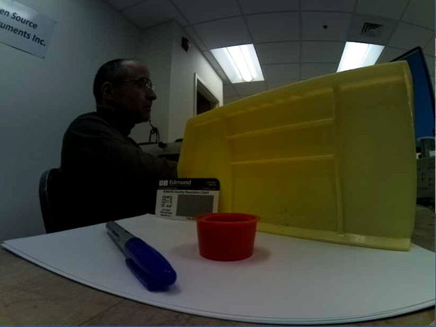
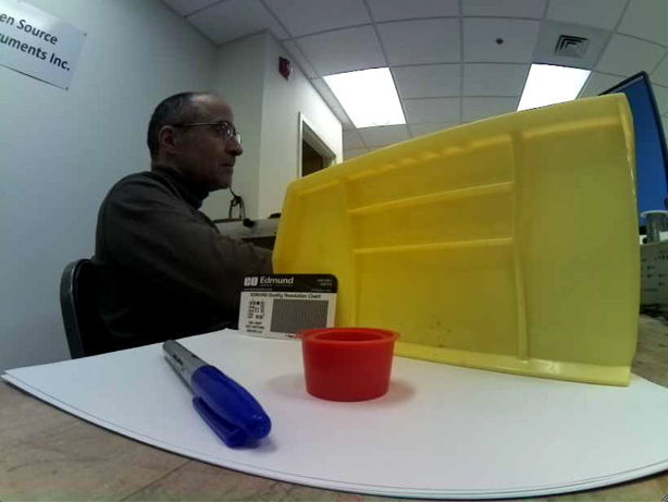
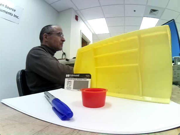
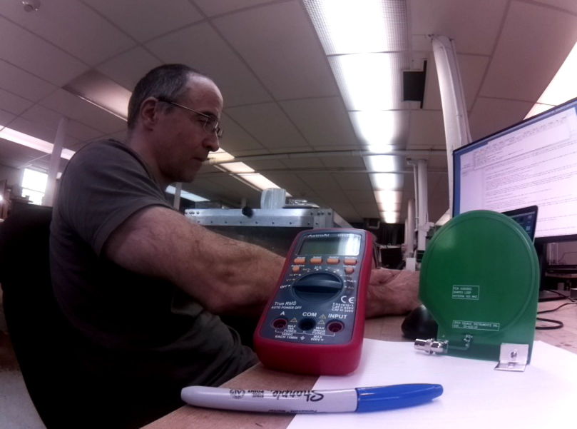
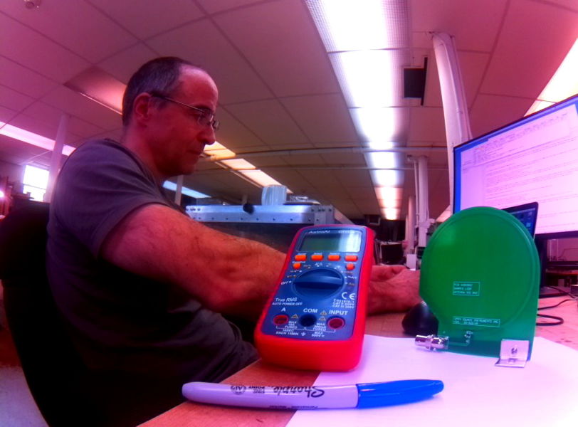
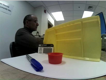
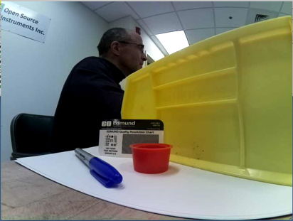
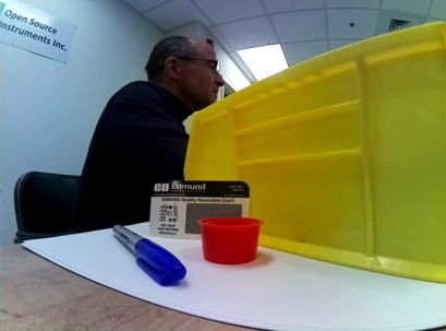
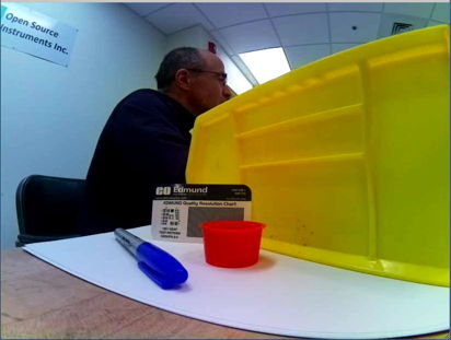
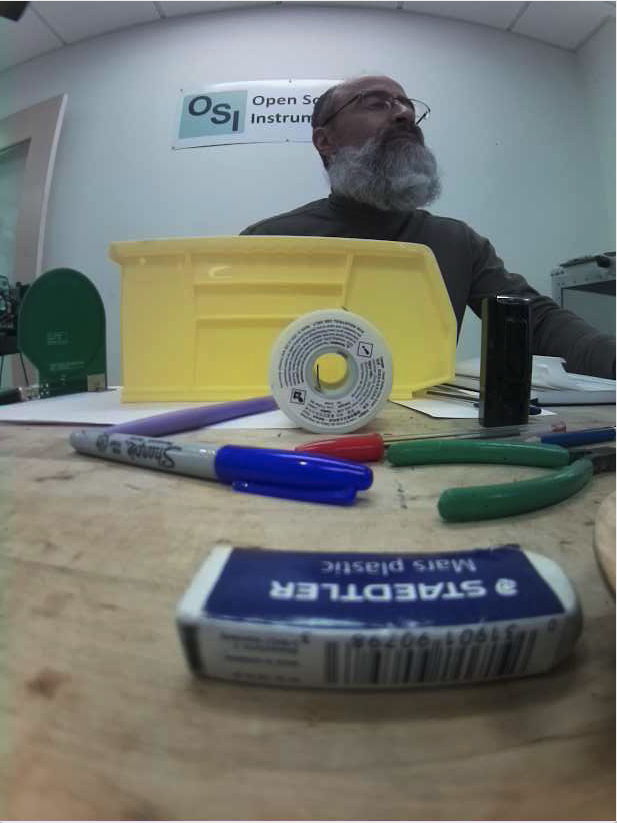
The above image shows near objects out of focus and distant objects in focus. The focal range of the camera is infinity, meaning we have made the focus sharp for distant objects. By default, we focus the A3034 at range 40 cm in the factory before we ship. You can adjust the focus by turning the lens and watching a live image.
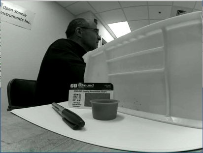
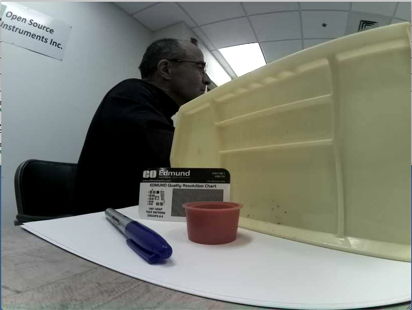
[09-JUN-22] The A3034 camera adjusts its exposure time automatically to suit the illumination in the image. But it can favor the dimmer parts of the image or the brighter parts of the image, and we control which parts it favors by setting its exposure compensation.
The Videoarchiver allows us to set the exposure compensation value to any integer between 0.0 and 1.0 with a menu button. Once recording begins, we cannot adjust the compensation without stopping and starting again.
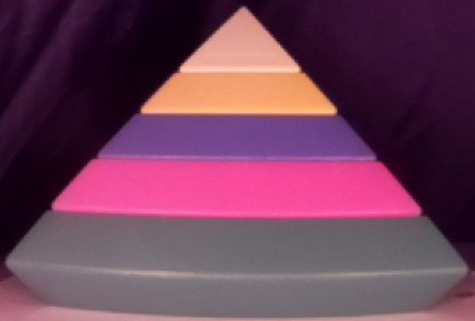
In the photos above, colors are rendered better because the lighting is better, but also because the A3034C2 provides better color balance, exposure compensation, and color saturation than the A3034C1 camera.
[21-JAN-23] In the Videoarchiver, we can adjust the brightness of colors with the color saturation value. The Videoarchiver allows us to set the color saturation to any integer between 0.0 and +1.0 with a menu button. Once recording begins, we cannot adjust the saturation without stopping and starting again. The photographs below shows how the saturation value brightens the colors in A3034C1 video.
The A3034C2 camera uses the libcamera video routines instead of the older raspivid routines. The result is superior handling of color brightness, as we can see in the example image below, taken from an A3034C2.
We recommend a saturation value of 0.5 for looking at animals in dimly-lit cages, but we leave it to the experimenter to find the value that gives the best color contrast for animal viewing.
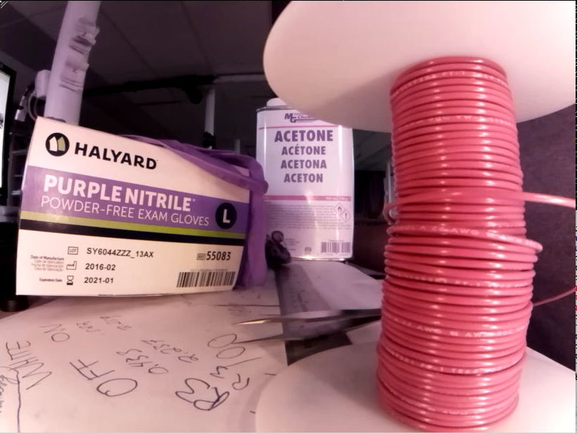
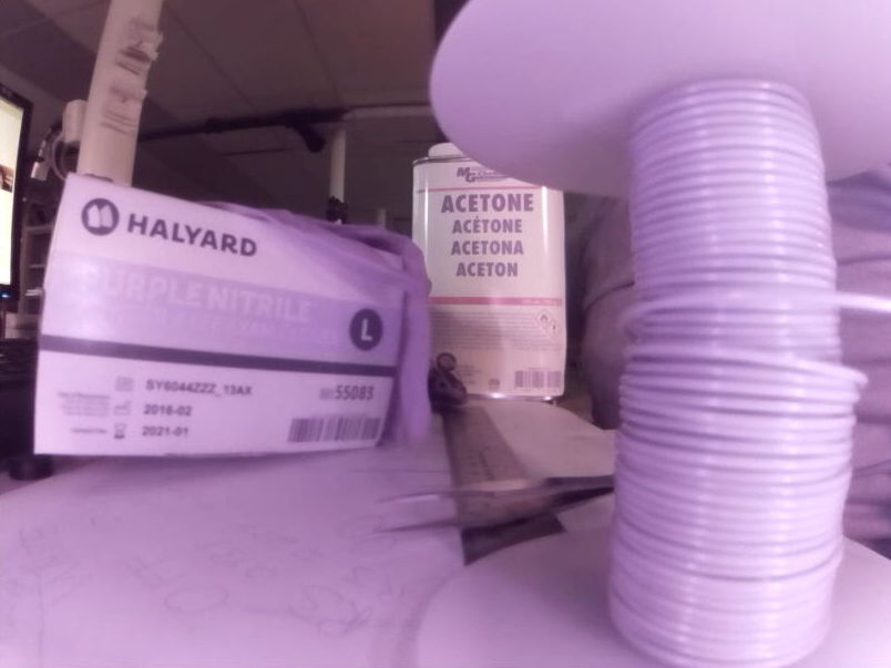
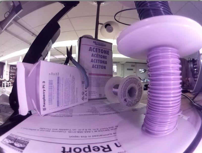
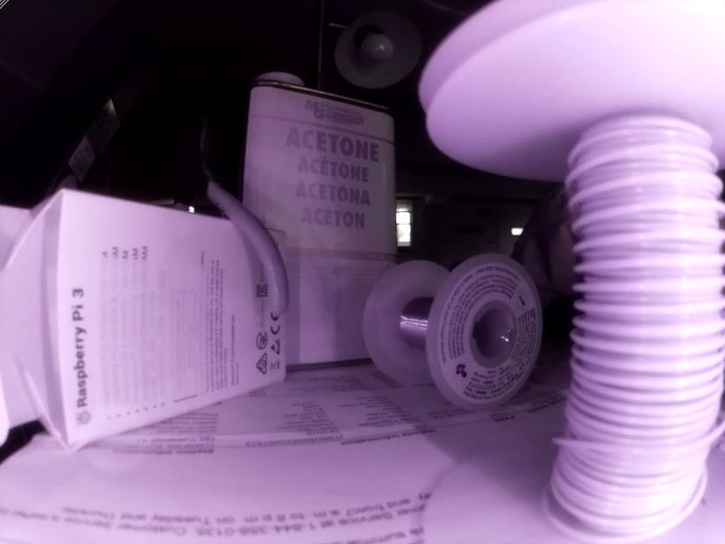
[15-MAR-24] A standard ACC is equipped with a lens that focus images of both visible and infrared light. The camera obtains gray-scale images by the light of its own infrared lights at night, and full-color images by its own white lights during the day. Sunlight contains infrared light as well as white light, so the images we obtain with the ACC in sunlight appear purple, as we can see in the image below, where the view out the windows is purple.
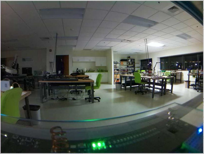
In white LED light, such as the white light provided by the ACC's white lamps, the IMX219 image sensor provides bright, accurate color images like the one shown on the left below.
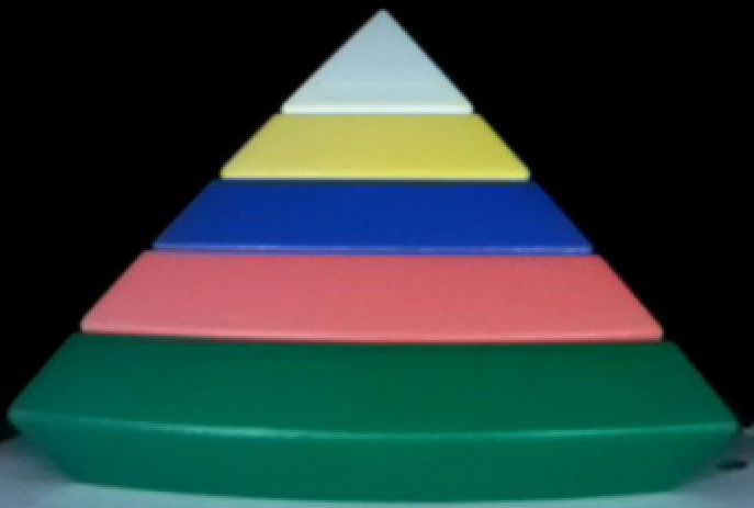
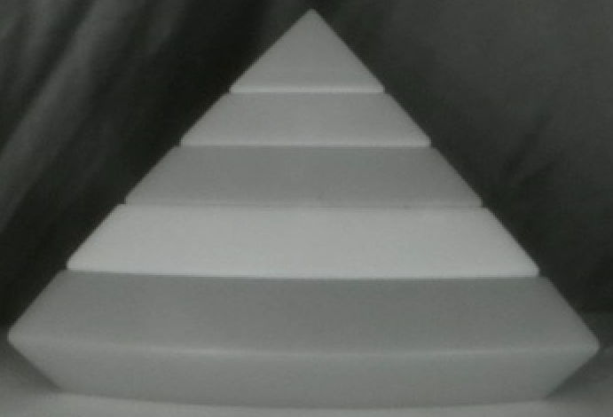
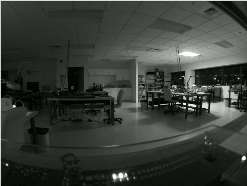
In infrared light, the camera provides a monochrome image. Its red, green, and blue pixels are all equally sensitive to infrared light, so no colors emerge in infrared illumination. When we mix the two, we get shades of red and blue, but green objects appear gray. Sunlight and incandescent lights provide a mixture of visible and infrared light. The ACC with its standard lenses provides poor color balance when viewing objects in natural light or in rooms lit with light bulbs. We can, however, equip the ACC with an infra-red blocking lens if your application uses natural light exclusively.
We do not have the relative response of the IMX219C image sensor, but we expect it to be much the same as that of the IMX334C, shown above. The A3034A's infrared emitter is the APT2012F3C, with peak emission wavelength 940 nm. Our white LEDs are the L130-2780, which appears to the human eye to be the same color as an object at 2700-Kelvin. The actual emission spectrum of the LED is not a black-body emission spectrum, as shown below.
The white LED is actually a blue LED covered with yellow phosphor. The result is a combination of blue and yellow light that appears to our eyes to be the white. The color of objects in this light, may not be the same as the color they would appear in incandescent or fluorescent light. We adjust the color balance of our cameras to provide the best colors in the light of the camera's own white LEDs. If you see variation in color balance across your camare field of view, try updating to the latest Videoarchiver and then updating your camera color balance with the update button. The update will install the latest color balance tables.
[23-OCT-19] The A3034X and A3034A were prototype versions of the Animal Cage Camera. We replace them with the all-purpose A3034C, which comes in a rugged, heat-dissipating, black-anodized enclosure, and may be mounted on a stand, zip-tied to a structure, or allowed to sit with the stability of its own weight upon a flat sufrace. We can adjust the focus of the lens by rotating it in its threaded holder. Two screws allow us to secure the lens during adjustment so that it does not move when we let go of it, or later when we move the camera. We can reset the camera's IP address by pressing the configuration button while the camera boots up. We can vary the intensity of the white and infrared LEDs. The A3034B was an intermediate version in which we did not implement full isolation between the chassis and the Power-over-Ethernet negative terminal, resulting in a device that could create ground loops when used with shielded cables.
S3034C_1: Animal Cage Camera Schematic for Version C.The S3034C_1 schematic shows the A3034AUX-C auxiliary circuit we add to the Raspberry Pi3B+ to provide Power-over-Ethernet (PoE) conversion, white LED lighting, infrared LED lighting, and a configuration switch. The earlier S3034B_1 shows the earlier A3034AUX-B circuit, which did not provide isolation between the PoE and the A3034 power supplies.
A four-way ribbon cable brings the four possible PoE voltages from the RJ-45 socket on the Pi3B+ and delivers them to P1, where a bridge rectifier generates the POE and 0V potentials. Transistors Q1 and Q7, along with zener diode Z1 and some resistors provide both PoE detection and connection. We describe the operation of this PoE switch below. Converter L1 CC10-4805SR converts 48-V PoE power to 5-V at 2 A for the Pi. Converter L2 CC3-4812DR converts PoE to 24 V for the LEDs. The white and infrared LEDs are controlled by separate four-bit DACs. The Videoarchiver presents buttons for power levels 0 to 4, which it maps onto the DAC values 0 to 15 to give a useful progression of output power. Switch S1 is examined by the Pi when it boots up, and if pressed will cause the Pi's Ethernet configuration file to be over-written by the factory default configuration, which is a static IP address 10.0.0.34.
The A3034 lens and image sensor provide superb video of moving animals in dim and bright light, both near and far from the camera. The Pi3B+ provides a graphical processing unit (GPU), and we enlist this processor to compress the twenty individual 820×416 frames per second produced by our image sensor into high-resolution images. Despite the compression of the individual frames, this video still occupies 2 MByte/s on disk. When compressed by the inter-frame H264 algorithm (with quality setting crf=23), the video occupies only 40 kByte/s and retains all the clarity of the original. If we are to connect ten such cameras to a single data acquisition computer, we must either compress the video in the camera itself, or compress the video on the computer. Even a gigabit Ethernet will be unable to transfer 200 MByte/s continuously. And even a powerful desktop computer will be burdened by the job of compressing ten video streams in real time. Thus the A3034 must perform its own compression. During recording, the Videoarchiver synchronizes the clock on each camera every few minutes, and each camera records its video into one-second segments that begin and end on the one-second boundaries of its clock. The Pi3B+ has four microprocessor cores each running at 1.4 GHz. We use three of these to compress the video segments in parallel. The data acquisition computer has only to download the compressed segments and concatenate them into files with timestamped names. This it can do easily for ten cameras over a gigabit Ethernet.
The A3034C1 and A3034C2 differ in their internal video-handling software. The C2 provides better color balance, especially after updating with Videoarchi ver 34+. Two determine whether your camera is a C1 or C2, use the Q button in the Videoarchiver to query the camera. If the camera's operating system is listed as "Bullseye", it's a C2. Otherwise it's a C1.
Each A3034 provides a file "videoarchiver.config" that contains text lines identifying its operating system and hardware configuration. Right now we have two versions of this file. The first, which is present on A3034B and A3034C1 cameras, is as follows.
sensor IMX219
platform Pi3+
assembly A3034B
The second, which is present on A3034C2 and A3034D2 cameras, is as follows.
sensor IMX219
platform Pi3+
assembly A3034B
os Bullseye
The purpose of this file is to let the Videoarchiver know what image dimension, frame rate, and video libraries are available on the camera. In both these examples, the IMX219 is the image sensor, which dictates the available image dimensions. The additional "os Bullseye" line we added to the C2/D2 cameras in order to inform the Videoarchiver that it should use libcamera routines rather than the older raspivid routines.
[11-MAY-18] The A303401A circuit board requires that we displace L1 and add wire links to accommodate an inverted footprint. The result is our A3034X with half and full-power visible illumination and full-power infrared illumination.
[09-OCT-19] The A303402C circuit board requires the following modifications. (1) A wire link between L2-2 on the component itself and the pad for L2-2 on the PCB footprint. (2) Cover the low-voltage end of R21 with two layers of kapton tape so it does not make electrical contact with the camera lens holder.
[19-OCT-19] We made 15 A3034B cameras using the A303402C circuit board. We will re-work this board for future ACCs, with these corrections.
[14-JAN-20] The A303402D implements the above changes. We distinguish the newer ACC by giving it assembly number A3034C.
A list of shell commands we have used to get things done in our tests, and in preparing Raspberry Pi disk images.
# The fdisk command (fixed disk) is available on all Linux and Unix platforms.
# Here use it to obtain a list of disks and partitions.
sudo fdisk -l

# Here we call fdisk on a disk so we can create partitions, then format with
# ext4 file system.
sudo fdisk /dev/sda1
sudo mkfs.ext4 /dev/sda1

# The mount command (mount a disk) attaches a partition to a directory. The
# directory must exist before-hand. If we don't specify a directory, mount looks
# in the /etc/fstab text file (file system table) for an entry that specifies
# where this device should be mounted.
sudo mount /dev/sda1 ~/Desktop/USB

# The unmount command (unmount a disk) detaches a partition from a directory.
sudo umount /dev/sda1

# The dd command (data duplicate) command copies files, channels, partitions, or
# entire disks with their boot partitions and tables. Here we copy the entire
# contents of the device /dev/sda to a file with extension img to mean "disk
# image". Note that we are not copying a partition, nor do we need to know
# anything about the structure or format of the device. We simply go to the
# first byte and copy every byte on the device until the operating system gets
# and end-of-file message from the device.
sudo dd if=/dev/sda of=A3034B_24MAR20.img

# We can use dd to copy a disk image file onto a device, overwriting as much of
# the device as required to accommodate the image. We don't specify a partition
# in the following command, only a device that will be written to, starting with
# the first byte of the device. We are also specifying that the dd command
# should indicate its progress as it goes along, and that it should copy in
# 1-MByte chunks, to speed things up.
sudo dd if=P3034B_24MAR20.img of=/dev/sda status=progress bs=1MB

# The following line in the fstab file creates a 64-MByte RAM disk mounted on
# the tmp directory.
tmpfs /home/pi/Videoarchiver/tmp tmpfs nodev,nosuid,noexec,nodiratime,size=64M 0 0

# We write zeros to all unused space on a partition with this use of dd, which
# reads zeros from the zero channel. We then delete the temp.txt file and we
# have all unused space as zeros.
dd if=/dev/zero of=temp.txt
rm temp.txt

# When we copy the drive to an image, we can now use the sparse file format to
# store the zeros simply as a number of zeros, rather than writing them to disk.
# A 16 GB image with 13 GB of zeros takes up only 3 GB as a sparse file.
sudo dd of=P3034B_24MAR20.img if=/dev/sda status=progress bs=1MB conv=sparse

# We can compress the sparse file and preserve its sparse format with the tar
# utility. Here we run the original image through tar with the -S option to
# preserve the sparse file, then with z we call gzip to compress further.
tar -cSzf P3034B_24MAR20.tar.gz P3034B_24MAR20.img

# We decompress the archive like this.
tar -xSf P3034B_24MAR20.tar.gz P3034B_24MAR20.img

# If we want to reduce the size of a partition, we must first make sure, as
# above, that we are going to lose only zeros. We use the gparted utility (gnu
# partition editor) to shrink partitions.
sudo apt-get install gparted

# List the block devices. Shows you the devices connected to the hardware,
# mounted or un-mounted. The list is presented as a tree, and provides the mout
# point directories when they exist.
lsblk

# The df command (disk filesystem) writes a list of all mounted devices.
df

# Run a video through ffmpeg to produce H264 compressed output in mp4 container.
# The ffmpeg input processor detects the input file type, first by checking the
# file extension, and then by checking the headers in the file, whichever works.
ffmpeg -i inputfile -c:v libx264 -crf 23 -preset veryfast output.mp4

# Shrink 820x616 video with ffmpeg down to half-size.
ffmpeg -i V1525694641.mp4 -c:v libx264 -preset veryfast -crf 23 -vf scale=410:308 shrunk.mp4

# Crop video to 720x900 with top-left corner of cropped region at x=0, y=100.
ffmpeg -i V1.mp4 -ss 00:00:00 -t 00:01:17 -filter:v "crop=720:900:0:100" V1_cut.mp4

# Read in a video and force key frames every half-second.
ffmpeg -i input.mp4 -force_key_frames "expr:eq(t,n_forced*0.5)" output.mp4

# Make montages of key frames so we can see them and count them.
ffmpeg -skip_frame nokey -i input.mp4 -vf 'scale=128:72,tile=8x8' -an -vsync 0 keyframes%03d.png

# Correct the frame rate of a video when the camera clock is off. Here we correct a
# ten-minute video containing 12004 frames in which the frame rate and time stamps
# give the video a length of 600.25 s.
ffmpeg -i infile.mp4 -filter:v "setpts=0.999667*PTS" outfile.mp4

# Read a video and print out information. The number of frames, for example, will be
# written after "frame=".
ffmpeg -i infile.mp4 -c copy -f null -

# Report on the network interface configuration, then disable the wlan0 and enable it.
ifconfig
sudo ifconfig wlan0 down
sudo ifconfig wlan0 up
| Version | Features | Image Sensor | Lens | Video |
|---|---|---|---|---|
| A3034X | Prototype circuit, stands above cage on four legs, no on-board compression due to lack of heat sink, separate power adaptor, 12 white LEDs, 12 infrared LEDs. |
IMX219 raspivid interface |
DSL215 | 820 × 616, 20 fps, H264, crf=23 |
| A3034A | Prototype circuit, zip-ties to structure or stands on floor, no on-board compression, separate power adaptor, 12 white LEDs, 12 infrared LEDs. |
IMX219 raspivid interface |
DSL224 | 820 × 616, 20 fps, H264, crf=23 |
[21-MAR-19] We have a new layout designed for mounting behind a cage in an IVC rack, by strapping to the two vertical pipes behind the cage. The A3034A is 140 mm × 100 mm. It provides the same visible and infra-red LEDs as the A3034X. It's DAC resistor arrays are fully-populated. The embedded processor sits in an enclosure mounted on the bottom-side of the board, while the camera looks out through the top-side. The LEDs are mounted on the top-side as well. We forgot to include a bridge rectifier to protect the converter. We add three two-pin connectors P3-P5 that allow us to add external infra-red and visible LED arrays to take the place of those on the circuit board.
[24-MAR-18] The A3034A and A3034X require their own 24-V power supply. We use the same power adaptor we provide with the LWDAQ Driver (A2071E) and Command Transmitter (A3029C). The power socket is marked +24V on the printed circuit board. The power plug is 5.5 mm outer diameter and 2.1 mm inner diameter, with the inner contact positive, see photograph of 100-250 VAC, 50-60 Hz adaptor with a computer power cable. These power supplies are generic, here is an example data sheet. We bring this 24-V power into a Faraday enclosure with a power jack bulkhead connector. The power socket of the connector faces outward and receives the plug of the power adaptor, see photograph of the cable and connector. Within the enclosure, the cable attached to the bulkhead connector plugs into the A3034.
The A3034A and A3034X operate at full performance for input voltages 18-24 V. For a 24 V input, when streaming live video with ambient lighting, the A3034 consumes 100 mA. When we turn on the visible LEDs to full power, the current consumption increases by 30 mA. When we turn on the infrared LEDs, the current consumption increase by 40 mA.
[25-MAR-18] We assemble the first prototype A3034A with circuit board A303401A. At power-up, the white LEDs shine brightly for less than a second, then go out. Two resistors over heat and burn. We find that U1, the current mirror, is suffering from thermal run-away. Our original circuit runs 2 mA through U1-6 at maximum brightness and expects 2 mA to flow through U1-3 as well. The two transistors are in the same SOT-323 and our assumption was they would remain at the same temperature. If U1-3 heats up, we expect U1-6 to heat up too, dropping its base-emitter voltage, and so controlling the current through U1-6. The base-emitter voltage drop for a given collector current decreases with temperature by roughly 2.4 mV/°C, as we show for diodes here. We find that for currents larger than 500 μA into U1-6, the current through U1-3 increases during the first few seconds. The LEDs turn off because U1-3 drops below the minimum 18 V required to provide current to the LEDs through Q2 and Q3. Instead, current flows through the base junctions of Q2 and Q3 into U1-3. When we have 20 mA flowing through U1-3 and 10 V, current dissipation in U1-3 is 200 mW, which exceeds the maximum for the UMX1 dual transistor.
[26-MAR-18] We change R1-R4 to 100 kΩ, 50 kΩ, 27 kΩ, and 14 kΩ respectively. At full brightness we have 400 μA flowing through U1-6. We remove Q3. We are powering only D1-D6. We have R6 = 270 Ω and R5 = 2.2 kΩ. We observe 1.7 V across R5, which implies 770 μA through U1-3. We do not have thermal run-away, but we have the U1-3 current is twice that of U1-6, which implies that the junction of U1-3 is around 7°C hotter than that of U1-6 (VT Ln(770/400) ÷ 2 mV/°C ≈ 7 °C). The voltage across R6 we assume is around 1.7 V also so we have 6.3 mA flowing through the white LEDs. If Q2, a ZXTP2025F has typical current gain of 380, we expect base current Q2-3 to be 20 μA ≪ 770 μA. We could decrease R6 to 100 Ω and so increase the LED current to 10 mA. The power dissipation in R6 will then be 10 mW, which is fine.
[27-MAR-18] We have R1-R4 all driven by the same 3.3 V and their resistance in parallel is 7.2 kΩ. The voltage across them all is 2.7 V for a current of 370 μA. Base-emitter voltage drop is 0.61 V. We have R6 = 100 Ω. Voltage across R5 = 2.2 kΩ is 1.5 V for 680 μA. Voltage across R6 is 1.4 V for 14 mA. We remove R6 and still see 1.5 V across R5, suggesting the base current drawn by Q2 is negligible.
We replace R1-R4 with a single 18 kΩ and see 2.8 V across it for 150 μA. We have R5 = 5 kΩ and 0.8 V across it, so 160 μA. The voltage across R6 = 100 Ω is also 0.8 V for 8 mA into the LEDs. We load Q3, D7-D12, and R7 = 100 Ω and see 8 mA flowing into the new diodes. The voltage drop across both chains of LEDs is 16 V for average forward drop of 2.7 V per diode. We load 5 kΩ for R15 and 18 kΩ for R10, to which we connect 3.3 V. We load D15-D26. We get 8 mA through the twelve infra-red diodes. Pin Q5-1 is at 15 V, making the average forward drop of the diodes 1.25 V.
We test the visible and infra-red illumination for image-taking in a cage. The visible illumination is bright. Our visible LED is the white L130-2780 of the Luxeon 3014 series. It is a 2700K warm white emitter in a P1206 package. The infra-red illumination is too dim for us to obtain a blob image of a toy mouse. The infra-red is the XZTHI54W. It is an 880-nm emitter in a P0805 package. According to its data sheet, this LED should emit a minimum of 2π × 0.8 mW = 5 mW of infra-red light at 20 mA forward current, or 2 mW at 8 mA. We drop R14 from 100 Ω to 27 Ω and R10 from 18 kΩ to 10 kΩ. We now see 1.0 V across R14, so 37 mA flowing through LEDs. The LED forward voltage is now 1.38 V. We put an SD445 photodiode up agains one of the LEDs and get 3.4 mA ÷ 0.6 mA/mW = 5.7 mW of infra-red light for an input power of 50 mW, or 11%. We drop the current to 10 mA and see 1.9 mW or 13%. We try an HSDL-4400 with 37 mA and get 4.1 mW. We restore the original LED. Our white LEDs at 8 mA give us photocurrent 2.8 mA. Assuming an average wavelength of 500 nm this is 11 mW. The electrical input power is 100 mW, so efficiency is around 11%.
[04-APR-18] We choose new DAC resistor values R4 = 40.2 kΩ up to R1 = 316 kΩ for the visible light control and R13 = 20.0 kΩ up to R10 = 160 kΩ for the infra red light control. Assuming the U1 and U2 base-emitter drop is around 0.6 V and the logic HI is around 3.3 V, we expect the following control currents versus DAC count.
Assuming that the control currents are mirrored exactly by U1 and U3, we calculate the visible and infra-red LED current versus DAC count. We have R5 = R15 = 4.7 kΩ, R6 = R7 = 100 Ω, and R14 = 27 Ω.
The maximum forward current of our infra-red LED is 50 mA. We expect to be just under the maximum at 44 mA for full brightness. The maximum current through the white LED is 120 mA and our maximum current is 6 mA. We remove our photodiodes D13 and D14 and replace them with phototransistors one hundred times more sensitive to light, and set R8 = R9 = 20 kΩ.
[13-APR-18] We have two A3034X, W0381 and W0382. We are shipping W0381 to ION along with ALT V0385. The Raspberry Pi username is pi@10.0.0.234 and password is "osicamera".
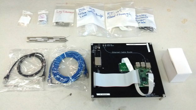
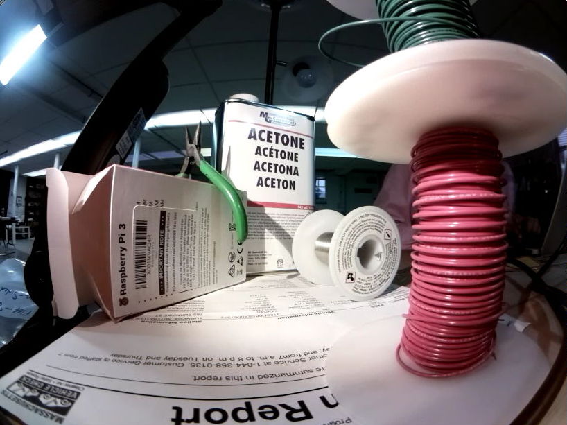
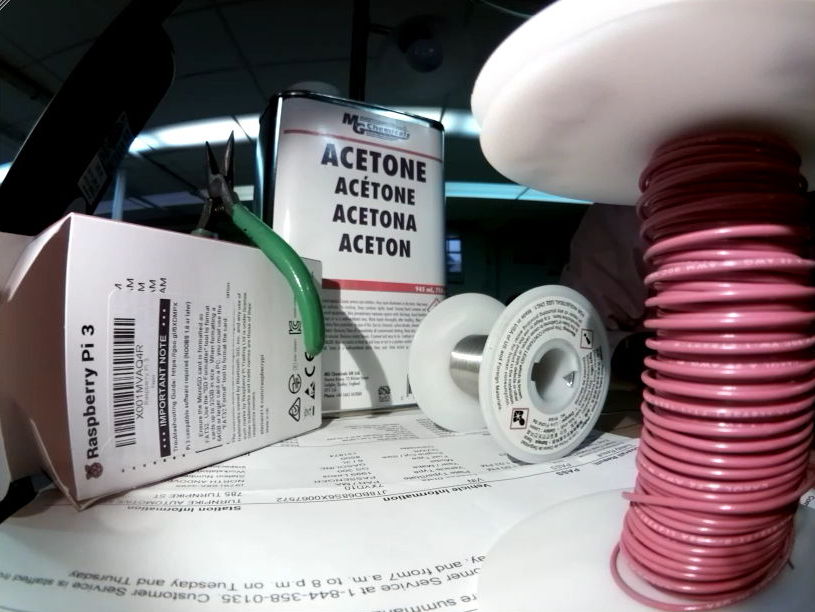
In the figure above we see two network cables and an RJ-45 feedthrough to carry the Ethernet connection from a local area network hub to the A3034X. The power adaptor is in a white box, and its bulkhead connector is in a bag. We have standoffs to raise and lower the camera, cable ties to fasten the network cable to the circuit board, extra flex cables for the camera connection, and wider-angle lens for use with the camera.
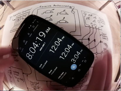
[24-APR-18] We have two videos of a cell phone clock, one 14-s long, the other 100-s long. We compress both with all eight ffmpeg compression speed settings, which we activate with options like "-preset veryslow". We leave the image quality at its default value, which we specify with "-crf 23".
ffmpeg -i inputfile -c:v libx264 -crf 23 -preset veryfast output.mp4
The "crf" stands for "constant rate factor". When this parameter is 0, the compression is lossless. When it is 51, the quality is the lowest possible with the H264 encoder.
We are surprised to see that veryfast gives the smallest file. We try a 30-s video half of which is partly taken up with our hands moving and adjusting the phone under the camera. We use a script stored in Scripts.tcl.
We make a 30-s video in which our hands are moving the phone continuously, with a diagram as a background, and repeat our measurement.
We pick "veryfast" as our preset value. It's three times faster than the default, and the files are the same size or smaller. We expect the maximum size of the compressed videos to be around 150 kBytes/s when many objets are moving quickly, and the minimum size to be 10 kBytes/s when nothing is moving.
[08-MAY-18] We consolidate all scripts into a single directory. We make all ffmpeg and mplayer calls directly from Tcl. A watchdog process, defined in Tcl, runs independently and monitors the segment directory. If the ffmpeg segmentation process is abandoned by the Videoarchiver, the watchdog will terminate the segmenter when there are more than a maximum number of files in the segment directory. We record for fifteen minutes on MacOS and obtain fifteen 20 fps, H264 video files each exactly one minute long, each beginning with our cell phone clock at 01 seconds. We do the same thing on Windows, but the file vary in length from 55 s to 65 s. In one example, ffprobe tells us that the video length is 64.1 s, there are 1282 frames, and the frame rate is 20 fps. We combine 9 such videos together to form one of 542.85 s (9:03) duration and 10857 frames at 20 fps. The time on our phone clock is 8:43:12 at the start and 8:52:14 at the end.
With nothing moving in the field of view, our compressed 1-s video segments are 56 kBytes long, with our set-up diagram as a background. With the phone clock in view, they are 62 kBytes long. With our hands spinning the phone the files are 250 kBytes.
To help with off-line development of the Videoarchiver Tool, we implement a virtual video feed in the Videoarchiver that we can activate with virtual_video. The feed reads a video file in the Virtual directory once and streams it to a local TCP port. We use the ffmpeg -re option to request that the input file be streamed at 20 fps, but it appears that this frame rate is not enforced. The files we record with the virtual feed are marked as having twenty frames per second, but they are stretched out in time. A one-minute video of 20 fps loses the first three seconds and lasts for 64 s.
[08-MAY-18] We compress a five-second movie of five white rats moving around in a cage. With the veryfast algorithm, the file is 1.3 MBytes. With veryslow it is 1.2 MBytes. We can crop a video stream with ffmpeg, and extract sections of a video as well. The following command extracts the interval from time 00:00 to 01:17 and preserves only the rectangle with top-left corner x=0, y=100, width 720 and height 900 (pixels).
ffmpeg -i V1.mp4 -ss 00:00:00 -t 00:01:17 -filter:v "crop=720:900:0:100" V1_cut.mp4
In mplayer we can jump to a particular time in a video with:
mplayer -ss 01:30 Blob_Track.mp4
These features will permit us to navigate through video files to particular locations to match EEG recordings. We can operate mplayer in slave mode to have it play video files that do not exist at the time we open the player window.
mplayer -slave -quiet -idle -input nodefault-bindings -noconfig all
loadfile V1525694641.mp4
pausing seek 30 0
We start mplayer in slave mode and tell it to idle when it's done playing a video. We also override all video screen key bindings so the user cannot quit, pause, or otherwise divert the playback with the mouse and keyboard in the video window. We deliver commands via stdin in this example (the keyboard). We load a video file, then seek absolute time 30 s and pause.
[10-MAY-18] We have nine recorded files each nominally 600 s long. Their names all end with 488. According to ffprobe, the frame rate is 20 fps. Eight have either 12004 or 12005 frames and one has 11981 frames, for a total of 108016, an average of 12001.8 frames in each 600-s video.
[07-JUN-18] At ION/UCL we record clear and synchronous video from an A3034X and A3032C of one mouse in a cage.
[12-APR-19] We connect a PT17-21C-L41-TR8 phototransistor to 3.3 V under our desk lamp and see 200 μA collector current. In over-head lights 130 μA, under a cloth 0.0 μA. Desk lamp directly on top 1.1 mA. In shadow 10 μA. We have both D13 and D14 on the same side of the A3034B. We load 20 kΩ for R8 and R9.
[19-APR-19] We ship A3034A numbers W0384 and W0385 with IP addresses 10.0.0.235 and 10.0.0.234 respectively to ION. We are left with A3034A number W0386 and A3034X number W0382. There is one more A3034X at ION, number W0381, with IP 10.0.0.234.
[23-APR-19] We can change the A3034 IP address by logging into its Raspberry Pi embedded computer. From a terminal on your data acquisition computer, use ssh, or "secure shell", to log in as the user
[07-MAY-19] Concatenating videos with ffmpeg is not as simple as listing two video files as input and specifying one output file. Here is how we concatenate two mp4 files in which the video is encoded with h264.
ffmpeg -i out1.mp4 -i out2.mp4 -filter_complex "[0:v:0] [0:a:0] [1:v:0] [1:a:0] concat=n=2:v=1:a=1 [v] [a]" \
  -map "[v]" -map "[a]" -c:v libx264 combined.mp4
The "filter_complex" that controls the concatenation is the string with lots of brackets inside. The [0:v:0] tells ffmpeg to take the first file (0:) and extract its first video stream (v:0), after which [0:a:0] extracts that same file's audio, and [1:v:0] and [1:a:0] do the same for the second input file. We want a "concat" filter function defined by the string on the right of the first equal sign, so the concat filter is "n=2:v=1:a=1" meaning two input files, one video stream, one audio stream. We have a final [v] [a] to give a name to the video and audio streams produced by the concatenation. Later, we have map commands to map the [v] and [a] streams into the output file. And for good measure we use the libx264 codec.
[09-MAY-19] We can record from more than one ACC on the same data acquisition computer, but we must be wary of using up the entire bandwidth of our Ethernet connection for the video streams, and of using up the computer's entire processing capacity for the compression of those streams. Even with resolution 820×616 and twenty frames per second, the data rate from each A3034 is around 2 MBytes/s, or 20 MBits/s. Five cameras streaming images across a 100-MB Ethernet will consume the entire Ethernet bandwidth. Either we must make sure we have Gigabit Ethernet, or we must install the cameras on separate networks. Another option is to reduce the resolution of the camera images to 410×308, which will reduce the network bandwidth by a factor of four. If you want to try this lower resolution, let us know and we will add support for it to the Videoarchiver.
[11-MAY-19] We test the ACC with 410×308, 1640×1232, and 3280×2454 resolution, and frame rates 5 to 40 fps. We find that the Raspberry Pi will not supply the 3280×2454 images. At 1640×1232, recording at 40 fps lags behind the incoming video stream, and we get video files that are shorter than their specified length, losing around four seconds every minute. At 20 fps recording works fine. We implement rotation of the image stream using the raspivid rotate option. Videoarchiver 3.6 provides menu buttons to set rotation, resolution, frame rate, and exposure compensation.
[21-MAY-19] We enable the A3034's interface by editing /boot/config.txt and commenting out the line that disables the wireless interface.
pi@raspberrypi:/boot $ cat config.txt
start_x=1
gpu_mem=128
dtoverlay=pi3-disable-wifi
We reboot to implement this change. We set the wireless network name and password with the raspi-config utility. The wireless interface connects to our local router, but our connection to servers outside our local network is intermittent. We disable the wired Ethernet with ifconfig eth0 down and the wireless interface provides reliable connection. We use apt-get to update the repository lists, then upgrade. We install ffmpeg and confirm that tclsh is installed. We now find we can use ffmpeg to segment the video stream into one-second mpeg files on the Pi. The following command runs in the background (need -nostdin for that) and writes its error-only output to a segmentation log file.
ffmpeg -nostdin -loglevel error -i tcp://10.0.0.236:2222 -framerate 20 -f segment \
	-segment_atclocktime 1 -segment_time 1 -reset_timestamps 1 -c copy \
	-strftime 1 S%Y-%j-%H-%M-%S.mp4 >& segmentation_log.txt &
We then use the following script to compress these segments.
set fl [glob S*.mp4]
set t [clock seconds]
foreach fn $fl {
  puts "compressing [file tail $fn]"
  exec ffmpeg -loglevel error -i $fn -c:v libx264 -preset veryfast V[file tail $fn]
}
puts "compressed [llength $fl] files in [expr [clock seconds]-$t] seconds."
It takes 74 seconds to compress 64 files. We are using only one of the Pi's four cores. We use the following tcl script to compress individual files.
set fn [file tail [lindex $argv 0]]
puts $fn
exec /usr/bin/ffmpeg -i $fn -c:v libx264 -preset veryfast V[file tail $fn] >& L[file root $fn].txt
And call it with this line using four cores.
find ./ -name "S*.mp4" -print | xargs -n1 -P4 tclsh single.tcl
The job is done in 40 s. With two cores, 49 s.
[22-MAY-19] We boot up a new Raspberry Pi with a keyboard, mouse, and monitor. We connect to the Brandeis University wired network. We add a key directory .ssh to the pi home directory, and we write the Videoarchiver's public key to a file authorized_keys. When we connect to the Pi without a password, the Pi uses the public key to encrypt a random number and the Videoarchiver uses its private key to decrypt the number and send it back to the Pi, thus proving the Videoarchiver's authenticity.
[23-MAY-19] We compress 74 MPEG 1-s segments on a Raspberry Pi 3B+. With -P1 to -P4 the process takes 97 s, 62 s, 53 s, 50 s. We set up two compression processes running continuously looking for segment files, while ffmpeg creates the segments from the camera stream, all in the Pi's Segments directory. With 20 fps and 820 × 616, the compression keeps up with segmentation. But when we ask for 40 fps, the compression cannot keep up.
[24-MAY-19] We record 60 ten-minute videos over-night and use ffmpeg to measure the duration of each. They are each either 600.20 s or 600.25 s long. We synchronize the W0383 system clock with our laptop clock and measure a 300-ms delay between starting a secure shell and setting the camera clock. We account for this latency and get the two clocks within 50 ms. Five hours later, the camera clock is lagging 1.5 s behind the computer clock.
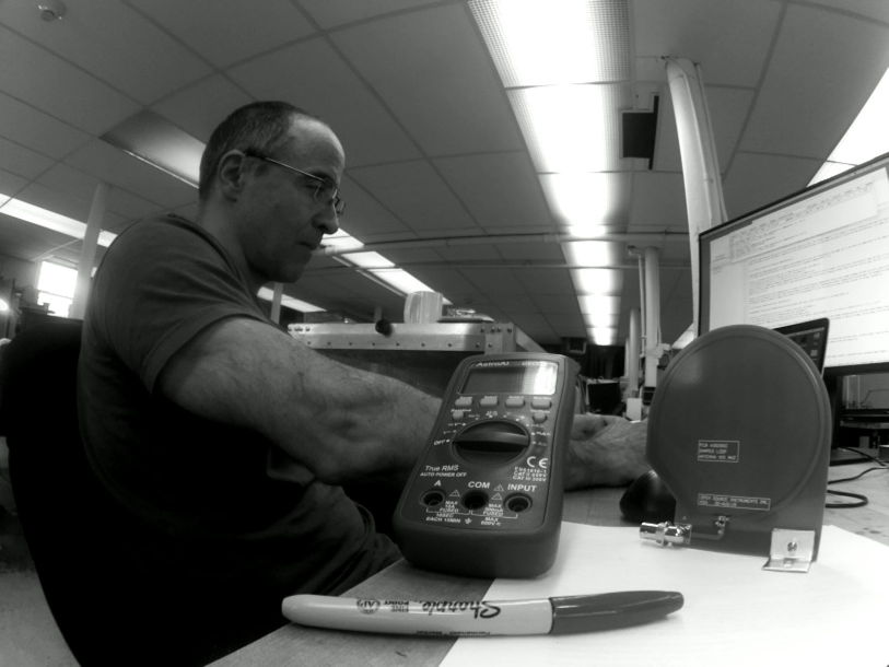
[30-MAY-19] We measure the time it takes one processor on our Raspberry Pi3B+ to compress one second of video at various resolutions and frame rates. The camera is viewing one person sitting at a desk and performing the measurements. Each measurement we make with fresh video.
[31-MAY-19] The size of our 820 × 616, 20 fps video varies with content. In darkness 0.1 MByte/min, slowly-changing illumination but no movement 3.5 MByte/min, steady illumination with some movement 4.5 MByte/min, steady illumination with constant full-field movement of arms and body 8.4 MByte/min. In the last video, the compressed one-second segments varied in size from 100-200 kByte.
When we leave the recording of 820×616 20 fps running for a while, with compression on the camera, we notice it starts to lag behind. With "vcgencmd measure_temp" and "vcgencmd measure_clock arm" we can measure the CPU temperature and clock speed. When we turn on recording, the CPU warms from 37°C to 60°C in a minute. The CPU clock speed is 1.2 GHz. After a few minutes, the CPU is at 82°C and the CPU is running at 926 MHz. After ten minutes, at 83°C the clock drops to 600 MHz.
[02-JUN-19] Yesterday we allowed the camera CPU to heat up to 85°C, its clock dropped to 600 MHz. We stopped the Videoarchiver and compression. Today its temperature is 45°C and clock is still 600 MHz. We reboot. Clock frequency remains 600 MHz. We cycle power. Clock frequency is still 600 MHz. We start recording. Temperature is soon 56°C and clock speed has increased to 1.2 GHz.
[03-JUN-19] We run three compressors -preset veryfast 820×616 20 fps on a Raspberry Pi3B without heat sinks, in a plastic case, board vertical, then add shiny heat sinks and repeat. We record clock speed and CPU temperature.
[04-JUN-19] Unless we specify otherwise, all our H264 compression is done with constant rate factor set to its default value of 23, which is half-way from maximum quality (-crf 0) to minimum quality (-crf 51). We record 410×308 at 20 fps with -crf 23, and monitor temperature and clock speed. We move around in the field of view. The ten-minute videos are around 15 MBytes, We switch to 820×616 at 20 fps, but with -crf 40, and monitor temperature and clock speed.
We compress a 10-minute 410×308 20 fps video from -crf 23 to -crf 40. Size drops from 15 MBytes to 1.5 MBytes. We compress a one-minute 820×616 at 20 fps video V1525694641.mp4 of size 7.4 MByte with -preset veryfast and -crf 23. Speed ×12.1, size 5.9 MByte, output looks the same as the input. We repeat with -crf 30. Speed ×13.8, size 2.5 MByte, quality slightly degraded. With -crf 40, speed ×15.7, size 0.9 MByte, quality greatly degraded, including some compression artifacts. We shrink the image with the following, and get ×27.4, size 2.1 MByte.
ffmpeg -i V1525694641.mp4 -c:v libx264 -preset veryfast -crf 23 -vf scale=410:308 shrunk.mp4
We expand the the shrunken image with:
ffmpeg -i shrunk.mp4 -c:v libx264 -preset veryfast -crf 23 -vf scale=820:616 big.mp4
Speed is ×14.0 and size is 4.9 MByte. Quality about the same as -crf 30 on original image with no shrink and expand. We shrink with -crf 10 (speed ×22.0) and expand with -crf 23 (speed ×12.4) and the result is almost as good as the original video.
[05-JUN-19] We find that our Raspberry 3B+ wireless interface is disabled, but there is no instruction in /boot/config.txt disabling the interface. It turns out that the interface is being blocked by rfkill. We unblock with "sudo rfkill unblock 0", reboot, and wlan0 interface is up. Add the line "dtoverlay=pi3-disable-wifi" to config.txt. Now the wlan0 is disabled on reboot.
We want to make 820×616 our default resolution with the IMX219. But if the CPU overheats, we want to kill the compressor processes and re-start them with lower resolution and slightly higher quality. When we display these in the Neuroarchiver, we will scale them by a factor of two.
set plist [split [exec ps -ef | grep compressor] \n]
foreach p $plist {exec kill [lindex $p 1]}
[06-JUN-19] We record from an IMX219 attached to a Raspberry Pi3B+ with shiny heat sinks. We monitor temperature and clock speet. Our HQLR test is 410×308 20 fps -crf 15. Our MQHR test is 820×616 at 20 fps -crf 23. The 1-s segments for both recordings are the same size: 60 kByte for no movement, 120 kByte for lots of movement.
So far as we can tell, the compression time lag in both recordings never gets above 7 s. The output files are a few seconds shorter than we specify. The verbose output in the Videoarchiver reveals that the transfer process is receiving and transferring segments out of order, so that a later segment arrives first, and we close one video with too few seconds, and a few jumps.
To support remote compression we now have a directory /home/pi/Videoarchiver that contains three essential files: compressor.tcl, interface.tcl, and videoarchiver.config. The latter contains the line "sensor IMX219" or "sensor OV5647" depending upon the camera module, and another line "platform 3B" or "platform 3B+". Videoarchiver 4.1 uses the configuration file to adjust its resolution settings. The interface script creates a TCPIP server to accelerate communication with the camera. The compressor script is what does the local compression of the segments created by a local ffmpeg segmenter. Both these scripts must be present on the camera for remote compression to work. If they are not present, remote compression will fail, but local compression will work fine.
We test sustained recording with local and rempote compression with IMX219/Pi3B, and OV5647/Pi3B+. We specify 20 fps. The one-minute files from the IMX219/Pi3B contain 1201 frames, and the ten-minute files contain 12005 frames. Thus the files appear to be 60.025 and 600.25 s long respectively. The frame rate from the IMX219/Pi3B is 20.008 fps. The one-minute files from the OV5647/34B+ are 1294 frames long, or 64.70 s assuming 20 fps.
[07-JUN-19] We connect an IMX219 to our Pi3B+ and record at 20 fps, asking for one-minute videos. One contains 1186 frames, the other 1161, when both should contain 1200 frames. The operating system running on the Pi3B+ has a graphical user interface, desktop, and many other installed features that our 3B minimal Linux does not have. The result of "uname -a" on this system is "Linux raspberrypi 4.19.42-v7+ #1219 SMP Tue May 14 21:20:58 BST 2019 armv7l GNU/Linux". We continue with the A3034A, with 3B and minimal Linux. The result of "uname -a" on this system is "Linux raspberrypi 4.19.42-v7+ #1219 SMP Tue May 14 21:20:58 BST 2019 armv7l GNU/Linux" also.
We equip our A3034A with dhcpcd.conf so it first tries to connect to a wired network with DHCP, then falls back to its static address. The wireless network is remains disabled with /boot/config.txt.
[10-JUN-19] We take the SD card out of our IMX219/3B camera and put it into our OV5647/3B+ camera. We request 20 fps and record one-minute videos. Four such videos each have either 1296 or 1297 frames. We take the SD card of our OV5647/3B+ and put it in our IMX219/3B camera. We obtain 11 one-minute videos at 20 fps and get 1200 or 1201 frames in each. Average is 1201.4. In ten-minute files we have 12004-12006 frames, so ffmpeg says they are 600.25 s long.
We compare heating in a Raspberry Pi3B with shiny heat sinks for 820×616 20 fps -crf 23 with local and remote compression. Heating with local compression is less than 5°C. With remote compression and no movement in the image, the temperature settles to 80°C and the lag is 4 s. But when we start moving in the field of view again, the temperature climbs to 84°C and clock speed drops to 800 MHz. The lag increases past 15 s and images are arriving out of order.
We prepare a new Raspberry Pi3B+ for use with the Videoarchiver and the IMX219. We load into enclosure and attach copper square heat spreaders and black anodized heat sinks. We connect the SD card to our laptop, create Videoarchiver in the boot partition, copy into this directory compressor.tcl, interface.tcl, id_rsa.pub, videoarchiver.config (says what kind of camera), and monitor.tcl (we use to monitor temperature). We move SD card to the Pi, to which we have a monitor connected. We use raspi-config to enable the camera interface, enable ssh, and set the password of the pi user. We add dtoverlay=pi3-disable-wifi to /boot/config.txt. We add net.ifnames=0 to /boot/cmdline.txt. We move the Videoarchiver directory into the pi home directory. We overwrite /etc/dhcpcd.conf with our dhcpcd.conf. We edit dhcpcd.conf to set the static IP address. We create folder /home/pi/.ssh and copy id_rsa.pub into this folder, renaming it as authorized_keys. We can now get live video, and we can record video with local compression, using Videoarchiver 4.3. We cannot perform a photo download because we don't have tclsh installed. We cannot perform recording with remote compression because we don't have tclsh and ffmpeg installed.
[11-JUN-19] We update Rasbian on our new Pi with "apt-get update" and "apt-get dist-upgrade", which takes thirty minutes. We follow with "apt-get install tclsh", and "apt-get install ffmpeg". We can now record with remote compression. We do so for forty minutes 820×616 20 fps -crf 23. The ten-minute files each contain 11599, 11563, 11573, and 11555 frames. We repeat for forty minutes at 410×308 20 fps -crf 15. These ten-minute videos have 11503-11552 frames each.
[21-JUN-19] We have a Raspberry Pi3B in plastic enclosure with shiny heat sinks. We try combinations of resolution, frame rate, and quality, and observe heating over ten minutes.
[26-JUN-19] We initiate streaming and segmentation on a Raspberry Pi3B+, and look at the number of frames in one-minute segments.
raspivid --codec MJPEG --timeout 0 --flush --width 820 --height 616 --framerate 20 \
	--listen --output tcp://0.0.0.0:2222 >& stream_log.txt &
ffmpeg -nostdin -loglevel error -i tcp://127.0.0.1:2222 -framerate 20 -f segment -segment_atclocktime 1 \
	-segment_time 60 -reset_timestamps 1 -c copy -strftime 1 S%s.mp4 >& segmentation_log.txt &
Each segment contains 1200 or 1201 frames. We record with local compression and the frame rate is 1200 fpm also. Only when we start to synchronize the Pi's clock with our computer clock, which we do with remote compression, do we get an inaccurate frame rate. With the timedatectl command we get "Network time on: yes".
We issue the following commands in the Pi terminal.
sudo systemctl stop systemd-timesyncd
sudo systemctl disable systemd-timesyncd
Now we get "Network time on: no". We record with remote compression. We see 1200 or 1201 frames in all one-minute segments except the first, which has around 1300. We reboot the Pi and our response to timedatectl is still "Network time on: no". We look for where this change to the default NTP setting has been made. The /etc/systemd/timesyncd.conf file has not been modified. The other files mentioned by "man timesyncd" don't exist.
[28-JUN-19] We are unable to turn off network time protocol on our Raspberry Pi3B with the commands listed above. The first command takes thirty seconds to complete and gives us "Warning: systemd-timesyncd.service changed on disk. Run 'systemctl daemon-reload' to reload units." Even after this, we will get "Network time on: yes". We load black heat sinks and copper heat spreaders onto a 3B and run at 820×616 crf=23 fps=20.
[16-JUL-19] We focus the camera at close range on the second hand of our digital clock, so that the changing digits fill the field of view. We start with no heat sink on the plastic package of the 3B microprocessor. We attempt to repeat the above heating experiment, but the processor immediately reaches 60°C and throttles back to 600 MHz, at which point compression cannot keep up with the video stream. We put a drop of silicone grease on the microprocessor, then set a 300-g column of aluminum on top to act as a heat sink. After ten minutes, the core temperature has risen from 35°C to 38°C. Ambient temperature is 25°C. We note that the 3B throttles back to 600 MHz when we deliver 5.0 V to our 50-cm power lead. We raise the supply to 5.2 V. We space the aluminum column 0.5 mm off the microprocessor and fill the gap with silicone grease and repeat our experiment. After two hours, the core reaches an equilibrium temperature of 54°C. The larger gap increases the core temperature by roughly 8°C. The aluminum block is at 42°C while ambient temperature is 26°C.
The following Tcl script to call ffmpeg and counts the number of frames in a set of video segments.
# Get the number of frames in a video.
set fnl [lsort -increasing [LWDAQ_get_file_name 1]]
foreach fn $fnl {
	catch {exec /usr/local/bin/ffmpeg -i $fn -c copy -f null -} result
	regexp {frame= *([0-9]+)} $result match numf
	LWDAQ_print $t "$fn $numf"
}
We collected a dozen 600-s files with the above experiments, and find they contain 12963-12965 images each, instead of 12000. We segment directly on the Pi and get the same result. The camera we are using is the UC-261 Rev B, which uses an OV5647 sensor. We segment with a frame size natural to the OV5647.
raspivid --codec MJPEG --timeout 0 --flush --width 640 --height 480 --framerate 20 \
	--listen --output tcp://0.0.0.0:2222 >& stream_log.txt &
ffmpeg -nostdin -loglevel error -i tcp://127.0.0.1:2222 -framerate 20 -f segment -segment_atclocktime 1 \
	-segment_time 60 -reset_timestamps 1 -c copy -strftime 1 S%s.mp4 >& segmentation_log.txt &
We have 1081, 1264, and 1084 frames in the first three segments. We connect a UC-350 IMX219 camera and issue the same commands. We get 1200, 1201, and 1200 frames per minute. We record 160 ten-second segments and obtain average 200.05 frames and standard deviation 0.5 frames per segment. We transfer SD card and camera to another Pi3B and get 20.00 fps. We
[22-JUL-19] We receive 15 of UC-350 cameras, IMX219 image sensor, no infra-red filter, 13-mm metal lens holder with set screw. We we pick one and record one hundred one-minute videos and find they have 1199-1201 frames in each.
[09-AUG-19] We have our first A3034B base plate, which provides a heat sink for the Pi microprocessor. We start by covering the Pi3B+ microprocessor package with white heat sink compound and placing on our table in open air. We connect a UC-350 camera (IMX219 sensor) and focus upon the seconds display of our digital clock, so as to provide movement for compression. We start recording 20 fps, 820 × 616 crf=23 and monitor temperature.
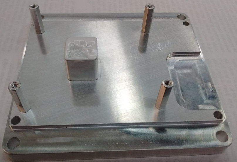
After ten minutes, the microprocessor has reached 62°C and appears to be stable. We mount on the A3034B base, orient the base vertically so convection can transport heat away from the outer surface of the base plage. After ten minutes, the microprocessor has reached 34°C, and is still warming up.
After thirty minutes, the Pi3B+ microprocessor has reached an equilibrium temperature of 40°C. The one-second compressed segments are 90 kBytes each. We set up four PT1000 RTDs with an A2053A to record temperature in four locations. We use heat sink compound to aid conduction to the sensors. When the camera is at equilibrium, the microprocessor is at 43°C according to its internal thermometer. The top of the heat sink column is at 40.5°C. The far side of the base plate from the heat sink column is at 39.5°C, top corner of the base plate is at 37.8°C, and ambient temperature is 25.3°C.
We have a 48-V PoE switch. We connect the switch to our Pi3B+, which has a four-pin plug called J14 (sic) for PoE power. We connect to pins 1 and 2, which are the connections for the Rx and Tx transformer taps respectively. The Rx tap turns out to be the negative power supply from this switch. Looking at the voltage between these pins, we see it jumping to 10V for a fraction of a once or twice a second. We connect a 26.5 kΩ resistor across these pins (ideal value is 25 kΩ). We see the voltage wavering around 5 V then jump up to 53 V and stay there for half a second before falling back to zero. We connect 1 kΩ through a switch. When we see the voltage jump to 53 V, we close the switch. The voltage stays at 53 V. While we are doing these experiments, we are streaming live video from the Pi through the switch, through another switch, to our computer.
[13-AUG-19] We have our Pi3B+ mounted on our aluminum base. We place the base face-down on the roof of our function generator. We load a DSL227 lens into a UC-350 camera, point it at our back while working at our bench, and record 20 fps, 23 crf, 820×616 in one-minute segments. After an hour we have fifty-nine complete segments. The first one has 1240 frames. Another, half-way through the recording, has 1163 frames. The rest are either 1200 or 1201. We look through the 1163 frame video, which reports length 58 s. We see nothing unusual in this segment, nor the one before or after. We are synchronizing the Pi clock to the DAQ clock every minute. The observed offset before correction is 60±10 ms. For the last ten minutes, the temperature of the microprocessor is 43.5±0.5°C.
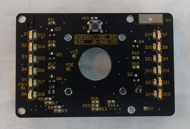
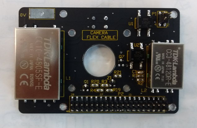
[16-AUG-19] We have the A303401C printed circuit board submitted for fabrication, see top and bottom drawings. Its outline matches that of the Raspberry Pi3B+, with mounting holes to place it on a column of standoffs. Its 40-way header sits on the bottom side of the board, in the same orientation as the Pi3B+ that will mount beneath it. Thew A303401C is for use in the A3034B camera, which operates with a single 100/1000 Mbps Power over Ethernet connection. It is equipped with PoE rectifiers (U1 and U2), reference load (R1 and R2), voltage-sensitive power switch (Z1, Q1, and Q7), and 48-V converters (L1 and L2) to produce the Raspberry Pi's 5-V at 2 A, and the LED's 24 V at 300 mA. The UC-350 camera board mounts on the bottom side, with its lens looking up and out the top side.
The A3034B provides LEDs in two arrays on the left and right side of the board, twelve each of white and infrared. Configuration switch S1 will permit restoration of factory default settings on power-up. The voltage-sensitive switch connects the POE (Power Over Ethernet) to VCC when POE reaches approximately 36 V. At 36 V, Z1 is conducting and we have 3 V across R3 and R20, which provides 1.5 V for the gate of Q1. Transistor Q1 is a ZVN3306F, with threshold voltage 0.8-2.4 V and typical 1.5 V at 100 μA. The drain of Q1 applies base current to Q7, which connects POE to VCC. Feedback resistor R21 raises the gate of Q1, thus providing hysteresis.
While Q1 is on, VCC ≈ POE. As POE drops, suppose we get to a point where Z1 no longer conducts, but Q1 remains turned on. The gate voltage is PEO×R20/(R20+R21) = PEO/51. When this is <0.8 V, Q1 will turn off, which occurs at 40.8 V. But for POE = 40.8 V, Z1 will be conducting, which contradicts our starting assumption. Thus Q1 cannot be on while Z1 is not conducting. We concern ourselves with the behavior of the switch while Z1 is conducting, as in figure above.
The power switch turns on at some voltage 35-38 V, and turns off at some voltage 34-37 V. The hysteresis in the switch is 0.8 V with respect to POE. The maximum collector-emitter voltage on Q7 is −38 V. The maximum gate-source voltage on Q1 is 13 V.
Today we obtain 100 one-minute video segments at 20 fps. The first has 1218 frames. All others have either 1200 or 1201 frames. The camera is base-down on function generator and reaches 44°C in ambient 26°C. Mount in our stand. Reaches equilibrium at 48°C at same ambient temperature. We obtain ten ten-minute segments, each containing 12000-12007 frames, size 40 MBytes, with me moving around in the field of view constantly by small amounts, which camera is held stationary.
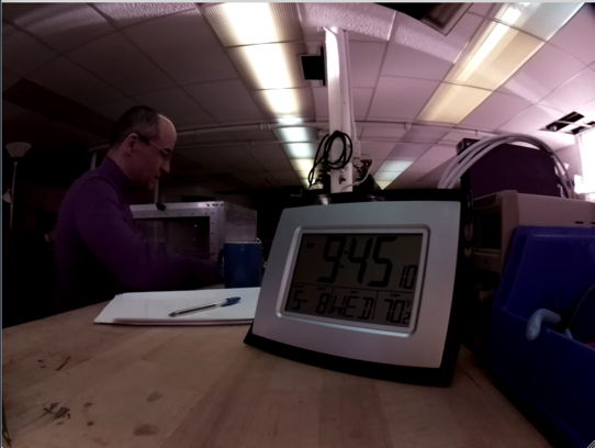
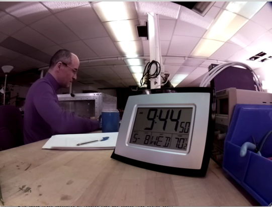
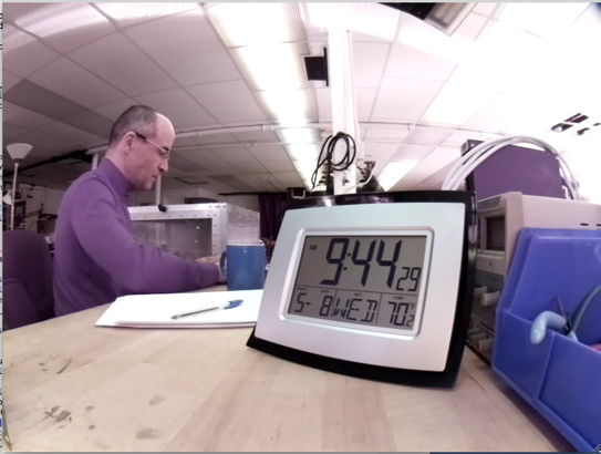
[26-AUG-19] Our A3034B prototype has been running continuously for three days, compressing video and recording to ten-minute MP4 files. On the same computer we have the Neuroarchiver recording from SCTs to NDF files. We have the A3034B camera looking at the computer screen, which shows computer time. We navigate through the video using the Neuroarchiver's clock panel. The video time and the computer time seen in the camera view agree to ±100 ms throughout the recording. When we look for an event in the NDF file, such as the addition of SCTs to our Faraday enclosure, or picking up a transmitter, we find that the NDF time of such events is three seconds greater (delayed) with respect to the video and computer time of the same event. We compare the computer time to our laptop time and see that our laptop time is three seconds greater (advanced) with respect to the computer. Our computer is not correcting its clock over the internet. The clock lags by roughly one second per day, while the clock in the Octal Data Receiver is accurate to 1 ppm and lags no more than 90 ms per day. When new NDF files are created, the Neuroarchiver 133 calculates the new file timestamp by adding the length of the previous file to the timestamp of the previous file. After a three days, the new files have a timestamp three days ahead of the computer clock.
[27-AUG-19] Today the video time of our continuous recording is up to three minutes advanced with respect to the computer clock in the camera view. One compression process on the camera has aborted. In the middle of the night, a twenty-frame segment caused the ffmpeg compressor to generate an error, which crashed the compressor process. We find that the compression did, however, complete, producing a coherent one-second segment. Applying ffmpeg to the original uncompressed segment we get the same error that caused the original crash: "[mjpeg @ 0x7fb938012600] error count: 69 [mjpeg @ 0x7fb938012600] error y=38 x=51". We modify the compressor script so it will handle such errors gracefully.
[30-AUG-19] We assemble the first A3034AUX-B Auxiliary Board, which provides power over Ethernet, an array of twelve white LEDs, an array of twelve infrared LEDs, and a push-button switch for resetting the camera IP address.
We assemble with a Raspberry Pi3B+ and connect to Power over Ethernet. We turn on the white LEDs and capture live video.
We change resistor values in the LED driver circuits so as to raise the full-power current to 30 mA in both the white LEDs and infrared LEDs. We leave the camera running continuously without a heat sink, recording 420×308 resolution at 20 fps, crf=23. We record from several SCTs at the same time.
[05-SEP-19] The camera has been running for six days. We have been checking synchronicity between the SCT and video recordings by opening the Faraday enclosure and picking up transmitters. Each time, including today, synchronization appears to be ±50 ms or better. We have 820 ten-minute video files. Average number of frames is 12004.4, standard deviation 0.5, maximum 12008, minimum 12003, except for the first video, which has 12023 frames. One-second segments vary in size from 15-80 kBytes in daytime, with transfer times 15-20 ms. We are using a PoE sixteen-way 10/100/1000 MBPS switch. The camera logs show no errors in the compression processes. Camera processor is at 54°C, ambient temperature is 23°C.
[09-SEP-19] We have been running for three days with 10 fps, 820×616 resolution, crf=23 on a Pi3B+ with no heatsink or enclosure, connected to our PoE adaptor, with the infra-red lights on. The microprocessor temperature settles to 60°C and clock frequency is 1.2 GHz. Synchronization between the video and the EEG recording is still accurate to within our ability to tell by examining the video of us picking up transmitters. Our 400 ten-minute videos have an average of 6001.1 frames, a maximum of 6002 (apart from the first one which has 6011) and a minimum of 5996 frames. Standard deviation is 0.5 frames.
[10-SEP-19] We turn the white L130-2780 LEDs to full power on our A3034B. The voltage across R11 is 3.41 V, implying current 34.1 mA through D1-D6, compared to absolute maximum 120 mA. The typical current gain of Q3 and Q4 ZXTP2025F is 350, so we expect 100 μA flowing into the base of Q3 and Q4. The current through R10 is 190 μA. The voltages applied to R6-R9 are 3.3 V, with 2.7 V across each, for a total of 260 μA. The voltage across R12 is 3.44 V, implying 34.4 mA through D7-D12. We turn the infrared XZTHI54W LEDs to full power and see 2.68 V across R18, implying 26.8 mA through D13-D24. The absolute maximum for these LEDs is 50 mA.
We have a Pi3B with a 32-GB SD card providing Rasbian and desktop. We insert the 16-GB SD card that holds our working P3034B Rasbian system, using a USB adaptor. We type "sudo fdisk -l" to list available partitions and disks. Our 16-GB card appears as /dev/sda. We clone the sda device with "sudo dd if=/dev/sda of=P3034B_10SEP19.img". This takes 30 min. Later, we insert another 16-GB SD card into the same USB adaptor and copy disk image onto the new card with "sudo dd if=P3034B_10SEP19.img of=/dev/sda", which takes 60 min. We repeat with "sudo dd if=P3034B_10SEP19.img of=/dev/sda status=progress bs=1MB". We get a status report as we go, and the process takes only 15 min, average copy speed 16 MB/s. We repeat with another SD card and the process takes thirty minutes. The first one was HC1-10, the second was HC1-4.
[13-SEP-19] We add the line "tmpfs /home/pi/Videoarchiver/tmp tmpfs nodev,nosuid,noexec,nodiratime,size=64M 0 0" to the Pi's /etc/fstab file, and create a directory tmp as the mount point of a 64-MByte ram disk. We modify the Videoarchiver to use the ram disk for storing video segments, so we don't wear out the flash memory with excessive write cycles during continuous video recording. We write zeros to all empty space on the SD card with "dd if=/dev/zero of=temp.txt". When this operation stops because there is no space for more zeros in temp.txt, we delete temp.txt. Now we copy the disk drive with "sudo dd of=P3034B_13SEP19.img if=/dev/sda status=progress bs=1MB conf=sparse". This operation creates a sparse file on the host SD card. The file appears to be 16 GB, but takes up only a 3 GB.
[17-SEP-19] We load the graphical version of the Linux partition editor onto our SD-Burner Pi3B system with "sudo apt-get install gparted". We plug our P3034B SD card into SD-Burner and reduce the size of its root partition by 1000 MByte. We have already overwritten all unused space on the SD card with zeros. We make a sparse disk image of the SD card using the dd utility. We truncate to 15 GB. We copy onto a new blank SD card and the result is a working P3034B root and boot system. Depending upon which 16-GB SD card we use, we have 500-1000 MBytes of unallocated space at the end of the SD card space. We burn this 17SEP19 image into a dozen SD cards, using both free USB sockets on SD-Burner, and each dual-burn takes around five minutes. We compress the image into a zip file P3034B_17SEP19.zip, which is 1.1 GB.
Our P3034B with ramdisk for segment storage and compression has been running for four days. Synchronization between EEG and video is better than ±100 ms. Temperature with heat sink stable at 42°C.
[24-SEP-19] We are able to use the Pi's on-board graphics processing unit (GPU) to compress MJPEG video segments by specifying the h264_omx codec in the compression ffmpeg command, in place of the libx264 we have been using so far. The GPU compression proceeds roughly twice as quickly as the central processing unit (CPU) compression we have been using. But we have only one GPU and three CPUs. The single GPU cannot compress 820×616 video at 20 fps with crf=23 in real-time. We set compression_codec = h264_omx and num_compression_cpu = 1 and find that the video falls behind by one second every ten seconds. Furthermore, the quality of the video is inferior to that produced by libx264. When we allow raspivid to compress with H264 using the GPU, we obtain continuous, compressed video. But the compression is inferior to that provided by our own ffmpeg procedure. Movements are blurred. And there is a delay of a quarter of a second between our movements and what we see on the video, despite a 1 GBPS connection.
[30-SEP-19] We have twenty-five sets of enclosure parts for the A3034B. They are not yet black-anodized. The final version of the base is smaller than the initial version. The heat sink block is 0.6±0.2 mm shorter than the distance between the microprocessor package and the base plate. We place a 1-mm thick, 15-mm square, compressible, heat-conducting pad on the Pi microprocessor package. We press our aluminum heat sink column on top of the pad. We put a drop of carbon-based conducting grease on the end of the column. We assemble the Pi onto its base plate. The compression of the pad keeps the heat sink in place without glue or screws. By sticking the heat sink on the pad in the first place, we guarantee alignment without an assembly fixture. We assemble two A3034Bs onto their base plates in this way. We have our original A3034B on the prototype base plate, in which the gap between the microprocessor and the base plate was 0.3±0.1 mm, and the block is super-glued to the base plate while the gap is filled with white heat sink grease. We run all three at 820 × 616, 20 fps, 23 crf. After an hour, the original reports core temperature 45°C and the two new ones 47°C and 49°C. We add walls and cover to one at 47°C. After an hour its core is at 57°C. Ambient temperature is 23°C.

[08-OCT-19] We have three black-anodized A3034B assembled and recording 820×616, 20 fps, crf=23. After two hours, their microprocessors report core temperatures 51.0°, 52.1°C, and 51.5°C. Ambient temperature iss 22°C and our open-sided A3034B core is at 42.9°C. Before anodizing, the cores reached 35°C above ambient. Now they are 30°C above ambient.
[09-OCT-19] We observe voltages POE, VCC, and the drain of Q1 (Q1-1) after we plug our Ethernet cable into an A3034B. To get to these voltages, we disassemble the camera.
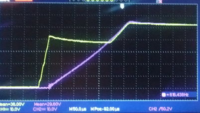
The PoE voltage rises until Q1 and Q7 start to turn on, and then halts and reverses, which causes the drain of Q1 to oscillate.
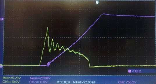
When we use a shielded cable to connect the PoE switch to a camera, the switch does not always recognize that a 12-W device has been attached. The PoE light over the socket does not illuminate. But power is nevertheless connected to the camera. The camera boots up, and we can record video. When we turn on the white lights, however, the switch turns off power to the camera, and possibly one or two other cameras connected to the switch. We consider our S3034B schematic and note that PoE current flows out of the local 0V and Ground through one diode in either U1 or U2 to the PoE negative supply. If the shield of the Ethernet cable is connected to Ground by the Pi, and to the PoE negative supply by the PoE switch, then current can flow directly down the shield to the PoE negative supply rather than through the diode. The fact that the current does not return along the expected cable conductor appears to be confusing the PoE switch. In the long run, we can fix this problem by isolating the PoE circuit from our 0V and Ground. Our two DC-DC converters L1 and L2 are both isolating.
We place a camera with base plate only, not cover, in our Faraday enclosure on an insulating platform with an unshielded cable to the Faraday enclosure wall, and another unshielded cable from the Faraday enclosure to the PoE switch. We record video and turn on and off the white LEDs. We are recording from a transmitter in water. We connect and disconnect the camera for various positions of the single antenna. The camera has no effect upon reception. We remove the transmitter from water. We see 120 μV of 60 Hz. We disconnect the cable from the camera. We see 60 μV of 60 Hz. We disconnect the Ethernet cable on the outside of the Faraday enclosure, see <5 μV of 60 Hz. We reconnect Ethernet, but now use a shielded cable inside the Faraday enclosure. We see <5 μV of 60 Hz.
[10-OCT-19] After running overnight, watching the lights flashing on an Octal Data Receiver, our four A3034B assemblies with heat pad on their microprocessors have core temperatures 53-54°C with ambient temperature 23°C. We re-build one camera with copper tape around the heat sink column to make it longer, and heat sink compound on each end of the column, which now fits snugly into the available space. We reassemble and leave running. After three hours it is at 54°C, while the two with silicone pads on their microprocessors are at 53-54°C and the original shiny base plate with no cover or top plate has its core at 43°C.
[11-OCT-19] We remove copper tape from the heat sink we modified yesterday, re-assemble with silicone pad and heat sink compound, but don't put the side walls in place. After two hours, its core is at 47°C, while our original prototype on a shiny base is at 43°C, and our two fully-assembled A3034B are at 52°C, with ambient temperature 22°C. Recalling our observations core temperature and clock frequency, the Pi3B+ runs at 1.4 GHz up to 60°C, then drops to 1.2 GHz from 60-80 °C, and 600 MHz above 80°C. A clock speed of 1.2 GHz is sufficient to sustain compression of 820×416, 20 fps, crf=23. Assuming that the core is always 30°C above ambient temperature, the A3034B should be able to operate at ambient temperatures 50°C.
[12-OCT-19] We try 40 fps with crf=23 and 420×308 resolution. The one-minute videos contain 2461±1 frames each. We try 30 fps, all videos contain 1801 frames. Movement tracking is superior in these low-resolution high-quality images, but fine detail of stationary objects is inferior. Core temperature of A3034B is 49°C, compared to 52°C when running our 20 fps, crf=23, 820×316 compression.
[14-OCT-19] We try 30 fps, 820×416, crf=23. The compression lag is stable for all four cameras at 4 s, core temperature for enclosed A3034B settles to 58°C. Ten-minute videos contain 18001-18004 frames.
[07-NOV-19] We are testing the MacOS version of Videoarchiver 15 on LWDAQ 9.1.4, which comes equipped with TclTk 8.6.9. We accumulate 391 ten-minute videos from five A3034B cameras. The first video recorded by each camera contains roughly 12010 frames. After that, the average is 12003.9, maximum 12006, minimum 11981.
[06-DEC-19] We have been running Videoarchiver 16 in one LWDAQ 8.9.6 process, and Neuroarchiver 137 in another, for 200 hours recording from four A3034Bs. One re-start occurred at 10 pm on Sunday 1st December. Other than that, recording has been continuous. Each day we find two or three jar-shakes in the Overview plot of the transmitter recordings, where we pick up the water jar that holds them, and shake it in the view of the cameras, and confirm that synchronization is perfect to within the resolution of this test, which is roughly ±100 ms. We have a thermocouple on the back wall of one camera, and we have been checking the back wall temperature twice a day. Today it is 34°C, with ambient temperature 20°C and processor temperature 49°C.
[17-DEC-19] We have been recording continuously for twenty days from four cameras pointing at a jar of transmitters, with our office in the background. There were two restarts during that period, both on Sundays, each applying only to one camera.
[19-DEC-19] We have four cameras running at low resolution with white LEDs on low-intensity, facing the flashing lights on the octal data receiver. Core temperature of S0216 is 45°C, back wall 34°C, ambient 19°C. Video files take up about 5 GByte/day. We return to high resolution.
[20-DEC-19] Camera S0216 back wall 34°C, core 49°C, ambient 21°C. Video files take up about 4 GByte/day.
[14-JAN-20] We have the A303401D circuit board ready to submit, which we hope will eliminate the ground loop problems we observed with the A3034B, and simplify assembly by moving components away from the lens holder.
[15-JAN-20] We start a list of commands we have used to get things done.
[21-FEB-20] We have our first two A3034C power boards build on the A303401D PCB. All footprints now correct. All parts clear of camera lens holder and standoffs. We connect to PoE switch, attach scope probe to 0V pad, and measure VEE and VCC. These two voltages appear to be floating with respect to the camera zero volts, which is connected to the shield of the Ethernet cable. We believe the PoE power is now isolated from the camera power.
[24-MAR-20] We use up all our P3034B_17SEP19 flash drives (16GB SD cards). We download our P3034B_17SEP19.zip backup and decompress to P3034B_17SEP19.img, which is no longer a sparse file, and takes up 15 GByte. We can't do this on a Raspberry Pi with a 16-GByte SD card, so we move to MacOS, where we decompress, then copy the non-sparse image with dd to a sparse file, copy the sparse file to an SD card, move the SD card to the Raspberry Pi, copy the image to its hard drive, and then write to another SD card with dd. When we try to use this SD card for an A3034B, we cannot update the camera firmware because the owner of all directories and files has been changed from pi to root.
We eventually manage to make more P3034B flash drives in the following way. We start by taking the flash drive out of an existing camera. We plug it into the Raspberry Pi. We use dd to copy the drive to an image file P3034B_24MAR20.img on the Pi's own hard drive. Copy this with dd onto another external flash drive, which is now a complete duplicate of the P3034B operating system and camera software.
[31-MAR-20] Of 20 of UC-350B camera boards we purchased, six have two missing parts and don't function, see photograph. We take these two parts off a board with a broken connector and load thme onto a board from which they are missing, and this board is now fully-functional.
[07-JUL-21] We find that our mplayer does not work on Fedora 34. We compile a stand-alone mplayer in the new operating system.
Download sources:

http://www.mplayerhq.hu/MPlayer/releases/MPlayer-1.4.tar.xz

Unzip and rename master directory as mplayer. Download codecs:

http://www.mplayerhq.hu/MPlayer/releases/codecs/essential-20071007.tar.bz2

Unzip and put in codecs directory parallel to mplayer directory. Install
zlib-devel and gtk2-devel:

sudo dnf install zlib-devel
sudo dnf install gtk2-devel

Now run configure and make:

./configure --codecsdir="../codecs" --enable-gui
make
The new mplayer won't run on our old 64-bit SLC6 (Scientific Linux 6.10) machine. We keep the new one and throw away the old mplayer. We drop support for video playback on 32-bit Linux.
[28-APR-22] We try out MPlayer 1.5 as installed by Home Brew on MacOS 1.15.7. We report the following problem to the MPlayer users forum. "I'm trying out MPlayer 1.5 installed on MacOS 10.15.7 by Home Brew. When I play a video, any video, with MPlayer 1.5, a window opens up on my laptop's display (2560 x 1600 Retina) with the video playing in the bottom-left quadrant, and the remaining quadrants are black. I have a second display connected to my laptop, one of lower resolution (1920 x 1080). I drag the window over to this second display and the video expands to fill the entire window. I move the window back to the laptop display and the video continues to fill the entire window."
We purchase twenty more Arducams from UCTronics, the ones marked UC-350 on the back, their part number B0103 without lenses for $51 each.
[11-MAY-22] We have our 20 UC-350 cameras from UCTronics. But they are UC-350 Rev D, not UC-350 Rec C. Our "Raspbian GNU/Linux 9 (stretch)" cannot open communication with the camera. If we plug in a RevC and reboot, we can then swap the RevC for a RevD and get video with the RevD. The manufacturer tells us that the RevD is compatible with "Rasbeery Pi Bullseye", but does not confirm that the RevD is not compatible with "Raspbian Stretch".
We plug a monitor, keyboard, and RevD camera into an A3034C and reboot. We enable wireless interface and disable Ethernet interface using instructions here. We can ping other devices on our local wireless network, but we cannot ping google.com. The wireless interface seems to have no gateway defined.
pi@raspberrypi:~ $ route -n
Kernel IP routing table
Destination     Gateway         Genmask         Flags Metric Ref    Use Iface
172.16.1.0      0.0.0.0         255.255.255.0   U     303    0        0 wlan0
We fix this with the following command:
pi@raspberrypi:~ $ sudo route add default gw 172.16.1.1
pi@raspberrypi:~ $ route -n
Kernel IP routing table
Destination     Gateway         Genmask         Flags Metric Ref    Use Iface
0.0.0.0         172.16.1.1      0.0.0.0         UG    303    0        0 wlan0
172.16.1.0      0.0.0.0         255.255.255.0   U     303    0        0 wlan0
Now we can ping google.com. We run sudo apt-get update followed by sudo apt-get full-upgrade. After reboot, we once again disable the eth0 interface, but we now find that the gateway is already defined correctly. The Pi cannot enable the RevD, even though the camera is detected and supported.
pi@raspberrypi:~ $ vcgencmd get_camera
supported=1 detected=1
pi@raspberrypi:~ $ raspivid -set
mmal: mmal_vc_component_enable: failed to enable component: ENOSPC
mmal: camera component couldn't be enabled
mmal: main: Failed to create camera component
mmal: Failed to run camera app. Please check for firmware updates
We load the RevC and reboot, then run raspistill -v and we see the video on our screen HDMI-connected display for five seconds. Note that we see the video on the HDMI display whether we run the command through an SSH terminal from our laptop or directly with the Pi's keyboard. Now we swap the RevC for the RevD without rebooting and we get video from the RevD with the same command.
We install Raspberry Pi Imager on our Mac. We create a "64-Bit Bullseye Lite" image on a 16-GB SD card. This version has no desktop, just like our existing Stretch image. Load into the Pi and reboot. We choose keyboard, specify user name "pi" and password "osicamera". With libcamera-hello we get an image from the RevC. We conect RevD without rebooting, get image. We reboot and we we get an error "failed to start camera".
We follow these instructions. We edit /boot/config.txt, setting camera_auto_detect=0 and adding the "dtoverlay=imx219" below "[all]" tag. We have the RevD plugged in and we reboot. The camera works.
We install tcl and ffmpeg. We over-write the existing /etc/dhcpcd.conf with our own. We add "dtoverlay=pi3-disable-wifi" to /boot/config.txt below "dtoverlay=imx219". We write the Videoarchiver public key to .ssh/authorized_keys. We reboot. We use the Videoarchiver's Update button write interface.tcl, compressor.tcl, dhcpcd_default.conf, and init.sh in the Videoarchiver directory. We write the following to /etc/rc.local to run our initialization script at startup.
#!/bin/sh -e
/home/pi/Videoarchiver/init.sh &
exit 0
We create directory Videoarchiver/tmp. We write the following to videoarchiver.config, using "Bullseye" as a camera that runs Bullseye.
sensor IMX219
platform Pi3+
assembly A3034B
os Bullseye
The Bullseye operating system does not provide raspivid. We change raspivid to libcamera-vid in the Videoarchiver Tool and we are able to get live images and record video, although the video is over-exposed and monochrome. We remove the saturation and exposure compensation options from the libcamera-vid call and the video looks good. We enhance the Videoarchiver to use videoarchiver.config to detect the ACC version and call raspivid or libcamera-vid accordingly. The gpio has been dropped by Bullseye, replaced by raspi-gpio. We edit init.sh to detect the ACC version and use the appropriate routine to flash the lights and detect the state of the configuration switch. Videoarchiver V25 includes the new code.
With Videoarchiver 25 and Stretch we get the usual response time and compression speed with view and recording. But with Bullseye we have a twenty-second delay for live video to start and compression cannot keep up with incoming segments. The processor heats up quickly. We cool it with freezer spray and it still cannot keep up with compression.
[12-MAY-22] We prepare a suite of test scripts in the Videoarchiver/test folder of our Stretch system. We have a script to start streaming, another to start segmentation, and others to compress the segments with one to four cores and measure the time taken. We prepare eighteen segments with movement. All segments contain 20 frames except the first, which contains thirty, and last, which contains 10, and one in ten segments that have 21 frames. We compress with four cores and the processor gets warm, but not hot, rate is 0.78 s/seg. With one core our rate is 1.28 s/seg. We add this test suit to Videoarchiver 25, and set it up so we transfer the test suite with the Update command, including creating the test subdirectory if it does not exist, with a new "mkdir" command in the tcl interface process.
We move to our Bullseye system, which we update with our test suite. We include RAM disk bound to tmp folder, as we describe here. We stop network time, as we describe here. All segments contain 20 frames except the last. We compress all of them with four cores at 0.89 s/seg but the processor is getting too hot to touch. We try recording video and the processor heats up fast. The live video takes eight seconds to start, compared to about four seconds for the Stretch system. We compress 35 files using one process. The CPU is warm. Compression rate is one per 1.57 s. Compress with four cores, processor gets hot, clock speed drops to 0.6 GHz. Rate is one per 1.00 s.
We create a 32-Bit Bullseye. Start with minimal distribution created on our Mac. Move to Pi with UC-350 RevC. Connect keyboard and monitor. Configure wireless interface. Turn off Ethernet interface. Install ffmpeg and tcl. Enable SSH. Secure shell from laptop over wireless network. Create videoarchiver.config and tmp. Re-write /etc/dpcpcd.conf, edit /boot/config.txt. Reboot. Secure shell over wired Ethernet. Edit /etc/fstab and /etc/rc.local file. Reboot. Write Videoarchiver public key to .ssh/authorized_keys. Update the system from the Videoarchiver. We get live video with the Videoarchiver. Our test suite is installed. We chmod +x init.sh, stream.sh and segment.sh. We now find that libcamera-hello gives horrible red video with our RevC camera, but beautiful high-definition video with the RevD camera, same in the Videoarchiver. So the RevC works well with raspivid but not libcamera-vid, while the RevD gives good video with raspivid once camera is enabled with RevC, but Stretch cannot enable RevD after boot.
We run our stream and segment processes to create a collection of videos with movement. Each image contains 20 frames exactly except the last. There are none with 21 frames. The first segment has exactly 20. Compress 54 frames with four cores. Processor gets warm but keeps running at 1.4 GHz. Rate is 0.74 s/seg. With one core, processor stays cool and rate is 1.31 s/seg. We modify Videoarchiver, remove Exposure Compensation parameter and replace with Saturation. Record video. We keep the processor cool by pressing it with our thumb. Lag jumps around 5-11 s, but the number of files in the tmp folder remains stable. When we view the video later, it contains jumps.
Move back to 32-bit Stretch system, we record and lag is 4 s for a couple of minutes. The processor is hot, but lag remains a steady 4 s. Processor speed drops to 1.2 GHz, lag remains stable. The video contains no jumps.
[16-MAY-22] Examining the jumpy video from the 32-Bit Bullseye system, the jumps are not consistent with the occasional out-of-place file. There appear to be missing files. We stop network time on the 32-bit Bullseye with commands given here and after reboot see that network time remains disabled. With the wireless disabled the network time can't be updated anyway, but we are happier with it turned off. We look at the segment files as they are created by the segment.sh test routine and see one missing out of twenty. Add warnings to Videoarchiver's transfer routine to point out missing, duplicate, or out-of-sequence segments. On our 32-Bit Stretch system, we have no missing segments, but on 32-Bit Bullseye we are missing one in five or six, as reported by the Videoarchiver's new warnings. We enhance the compressor to take a -verbose option and print segment names to its log file. We see segments being skipped because the compressor cannot find them. We ad "-map 0" to the ffmpeg segment command in the Videoarchiver because we see it often in examples. We add "-segment_list segment_list.txt -segment_list_size 1000" to generate a list of segments that we can examine for missing segments.
[17-MAY-22] In 32-Bit Bullseye with RevC camera we run segment.sh, now augmented to produce a segment list up to one thousand lines long. We run stream.sh and segment.sh and look at the list of files as well as the segment list. When we have 550 segments, we look through the directory listing. There are 35 segments missing. We look through the stream list and find 35 missing segments and 36 duplicates. In all cases, we have a missing segment, say S1652794988.mp4, and a duplicate with the next time stamp S1652794989.mp4. We are running ffmpeg 4.3 on 32-Bit Bullseye and 3.2 on 32-Bit Stretch. Enable wireless network on the 32-bit Bullseye. Uninstall ffmpeg. Look for available versions of ffmpeg, can find only 4.3.4. Reinstall 4.3.4. Disable wireless network. Our "-map 0" does not help. We remove "-map 0", but leave the segment list in place.
We modify segment.sh to give segments incrementing names starting at S1000000000.mp4 with "S1%9d.mp4" in place of "-strftime 1 S%s.mp4". We run stream.sh and segment.sh. Our list of 310 segments is complete and uninterrupted. The first segment contains 66 frames. Upon repeating our experiment, the first segment always contains more than 20 frames. But all the others contain exactly 20 frames. We restore timestamp file naming but change the segment length to two seconds. We get this report from framerate.tcl:
S1652797411.mp4 51
S1652797412.mp4 40
S1652797414.mp4 40
S1652797416.mp4 40
As the segments accumulate, we see all files incrementing by two seconds with none missing, except for the first, which is only one second younger than the second. The segment list and the directory listing agree. All segments contain 40 frames exactly except the first. The new ffmpeg is strict about the number of frames included in each segment except the first. It is not strict about incrementing the file name for each segment. We sometimes see a segment ending before the next clock second begins: the next segment might be named one second earlier than we expect.
When it comes to using segments longer than 1 s, we can force a key frame every second with "-force_key_frames expr:gte(t,n_forced*1.0)". When we concatinate files, we will still have key frames every second. In fact, we could force key frames every half-second so as to permit rapid navigation to half-second boundaries. We take a 3:22 video from our 03MAR20 test and force key frames every half-second with ffmpeg. We create montages of the key frames with another command.
ffmpeg -i V1583260383_Original.mp4 -force_key_frames "expr:gte(t,n_forced*0.5)" V1583260383.mp4
ffmpeg -skip_frame nokey -i V1583260383.mp4 -vf 'scale=128:72,tile=8x8' -an -vsync 0 keyframes%03d.png
The original contains 202 key frames, the new one 405. We try navigating to 0.5-s boundaries, but we see no improvement in performance. We force key frames every eight seconds, and now find we have only 26 key frames. The Neuroplayer is still able to navigate to 1-s boundaries. We note the amount of jerking at the start of each one-second interval and eight-second interval. We take the video with 26 key frames and force it to have 202. We see no improvement in navigation: we still see a one or two-frame repeat at the start of each new playback interval, as MPlayer navigates to the boundary. We discover a bug in the Neuroplayer, where we play the first frame of the next interval, which creates a flicker when we continue. We fix this, and now we get no flicker on one-second boundaries, where we have key frames, but lots of flicker and inaccurate repetition for half-second and quarter-second boundaries.
[18-MAY-22] We try two-second segments for recording with 32-Bit Bullseye and RevC camera. So long as the segment names increment by exactly two seconds, our compressors will pick out their own sequence of segments by comparing their process index (1, 2, or 3) with the segment timestamp modulo three (0, 1, or 2). But if we have irregularities in the sequence, one compressor will be burdened with two consecutive segments, and will fall behind.
S1652886860.mp4
S1652886862.mp4
S1652886864.mp4
S1652886865.mp4
S1652886868.mp4
S1652886870.mp4
S1652886871.mp4
S1652886874.mp4
S1652886876.mp4
S1652886878.mp4
We can instead give the files consecutive names, but we then lose the start time of the segment. We continue working with two-second segments for recording. In our segment list we see occasional repeats, especially in the first twenty segments.
S1652901375.mp4
S1652901376.mp4
S1652901377.mp4
S1652901379.mp4
S1652901381.mp4
S1652901383.mp4
S1652901383.mp4
S1652901386.mp4
S1652901387.mp4
S1652901390.mp4
Despite the duplication in the segment list, we see only one S1652901383.mp4 downloaded by the Videoarchiver in this experiment, and only one compressed in the compressor logs. Previously we did see the Videoarchiver downloading duplicate segments, but having inserted a duplicate warning, we see no further duplicates. We switch to a RevD camera. Picture is better. Navigation with one-second intervals fails with keyframes every two seconds. We use "-force_key_frames "expr:eq(mod(n,20),0)"" to add key frames every twenty frames (every second) to our segments. Now we see reliable navigation to one-second boundaries.
We work on the Videoarchiver until it is compatible with old cameras whose software has not been updated, and we use 1-s segments always with the Stretch system by detecting the software version using configurator.config. Comparing Stretch/RevC to Bullseye/RevD, the compressed twenty-second videos are half the size from the S/C system and always the correct length. The lag is no more than four seconds on S/C, and sometimes two seconds. The processor heats up in ten minutes. On the B/D system the videos are often 2 s too long, although file name timestamps match the video durations. The processor heats up in one minute. Our Videoarchiver 25 is now compatible with the old Stretch software, the new Stretch software, and the new Bullseye software. The RevC gives the same great performance on the old and new Stretch platforms. Old and new Stretch both use one-second segments. We have five RevC in-house, and another eight on the way.
[19-MAY-22] We begin with 32-Bit Stretch with Videoarchiver 25 software and RevC camera. We stream MJPEG video and create 1-s segments with ffmpeg 3.2. Each is 820x616. We accumulate 40 segments with movement, abort, and delete the last segment. Average segment size 2.4 MByte. First segment unusual: 41 frames, 80 kByte/frame. All others 20 frames, 100-120 kByte/frame, consecutive file names, with the following exceptional sequence (output from latest framerate.tcl).
S1652964565.mp4: 20 frames, 2325.8 kBytes, 116.29 kByte/frame
S1652964569.mp4: 16 frames, 1860.2 kBytes, 116.26 kByte/frame
S1652964570.mp4: 68 frames, 7896.7 kBytes, 116.13 kByte/frame
S1652964571.mp4: 20 frames, 2324.3 kBytes, 116.22 kByte/frame
Compress with ffmpeg 3.2 using -preset veryfast in 45 s, 1.15 s/seg = 1.1 s/s. Compressed files have same number of frames as originals. Average file size is 48 kByte, 2.2 kByte/frame.
Move to 32-Bit Bullseye with RevC camera. We stream with libcamera and use ffmpeg 4.3 to generate 2-s segments. We abort, delete final and have 30 left. We compress with ffmpeg 4.3 and "-preset veryfast", which takes 2.0 s/seg = 1.0 s/s. All uncompressed and compressed segments contain 40 frames except the first, which contains 79. Average uncompressed size 20 kByte/frame, compressed size 4.3 kByte/frame. We switch to RevD camera. Live video looks much sharper. We stream, segment, and compress 35 new 2-s segments. Compression takes 1.86 s/seg = 0.9 s/s. The number of frames per segment is 39-41, except for first with 72. Whenever the segment timestamp increments by one, the previous segment has 39 frames. Whenever the timestamp increments by three, the previous segment has 41 frames. Average uncompressed size 29 kByte/frame, compressed size 4.2 kByte/frame. We now record from the RevD. After a few minutes, processor is at 65C, but lag remains only 5 s. After 22 minutes, lag 6 s, 68C, and 1.2 GHz. Our 20-s videos look great, average size 2.2 MBytes, 5.4 kBytes/frame, 399-401 frames per video. We add del_first_seg option to Videoarchiver and turn off deletion of first segment.
We encounter occasional empty video segments, size 0.0 kByte, which causes ffmpeg to return an error. Restart failes because the temporary transfer file already exists. We add seg_min_size to reject such segments. We delete the temporary file on error. In the camera compressor logs, we see errors with the empty segment file names.
ERROR: error renaming "W1652975062.mp4": no such file or directory.
ERROR: File 'W1652975112.mp4' already exists. Exiting. during compression of T1652975112.mp4.
We set up to study this problem, but it does not occur again in forty minutes of recording. When navigating in the Neuroplayer, we find that the file timestamps are frequenctly off by one second in either direction, as in 20-s file marked 1000 followed by another file marked 1021 or 1019. Files either have 397-403 or they have 439 frames. Those with 439 frames are 22 s long. We see synchronization errors of up to one second. We turn on del_first_seg and repeat our experiment, watching an HMT on an antenna, tapping it occasionally and recording NDF for 300 s. Processor gets to 67C. Synchronization is within 100 ms.
We switch to 32-Bit Stretch with RevD camera (for which we must first connect RevC then replace with RevD). Video looks good, but not as good as RevC. Processor gets to 62C. Synchronization is within 100 ms. Go back to the older Stretch code that has not been updated for Videoarchiver V25, similar performance. Get warning in compressor logs about unknown option "verbose".
[04-JUN-22] We are seeing frequent segments of size 0.0 kBytes, which the Videoarchiver rejects, when working with a RevC camera and 32-Bit Stretch. It appears that our three compressors processes, which are trying to share the compression burden by renaming files and working on them once renamed, are colliding during the renaming process. We re-design the compression system. We now have a manager process that watches the incoming S*.mp4 segments, renames the oldest T*.mp4, and spawns a compression process to create a compressed file W*.mp4. When the compressor is done, it deletes T*.mp4 and exits. The manager knows the compression is complete because it sees T*.mp4 is missing. It renames W*.mp4 to V*.mp4 and this segment is now available for download. Because the S*.mp4 segments created by the ffmpeg segmenter are always appearing in chronological order, the manager starts compression in the same order, and keeps a list of the one or more compression processes that are currently running. The list is in order oldes to youngest segment, and the manager makes sure that the video segments V*.mp4 are made available in chronologica order too, so they will be downloaded in that order. It is now impossible for the Videoarchiver to receive segments out of order. The manager also watches for stalled compressors and for an accumulation of segments due to compression failing to keep up with the video stream.
[06-JUN-22] We run the top utility on 32-Bit Stretch recording from RevC watching us at computer, give top a ten-second delay. After a few minutes, we are using 37% of CPU, temperature is 61°C, clock speed is 1.2 GHz, lag 2 s. The raspivid process uses 2% of one core, we have 35% idle time. One-minute video 7 MByte and exactly 60 s. On 32-Bit Bullseye with RevC, same view and activity, we are using 47% of CPU, we have 11% idle time, temperature 64°C, clock speed 1.2 GHz, lag 7 s. The libcamera process is using 85% of one core and the ffmpeg compressors are using something like 20% each. One-minute videos 6 MByte and exactly 60 s except for the first one, which is occasionally 62 s, but timestamps give correct start and finish.
We work on a 32-Bit Stretch machine with Desktop GUI, keyboard, mouse, and monitor. We enable the Wifi on our 32-Bit Bullseye camera. On the Stretch machine, we run "sudo apt update", "sudo apt upgrade", install fpc with "sudo apt install fpc", install git with "sudo apt install git", install mplayer with too, and clone our LWDAQ repository with "git clone https://github.com/OSI-INC/LWDAQ". We eventually get LWDAQ running on the Pi, including the Videoarchiver. We get live video using the Videoarchiver on the Pi over the wireless network from the Pi camera. During the course of our experiments, we discover that the Bullseye camera interface does not support rotations 90° and 270°.
We want to see if we can have the Pi use eth0 to communicate with a LWDAQ server and wlan0 to communicate with the outside world. We enable the wlan in a 32-Bit Stretch machine by editing /boot/config.txt, then use the following lines for /etc/dhcpcd.conf.
controlgroup wheel
interface wlan0
static domain_name_servers=8.8.4.4 8.8.8.8
interface eth0
static ip_address=10.0.0.34/24
We have not defined a router for the eth0 interface. We define name servers for wlan0. We are not sure how the wlan0 gets its default gateway. It may be that the operating system remembers us running "sudo route add default gw 172.16.1.1", or it could be that this selection is automatic. We can now ping google.com and run sudo apt update. We upgrade all packages.
[08-JUN-22] We ordered the wrong lens holders from UCTronics. We need the holder with a square base less than 6 mm high. The ones we have are 8 mm high, so cannot mount close enough top the front wall, and our lens cannot get close enough to the image sensor to focus.
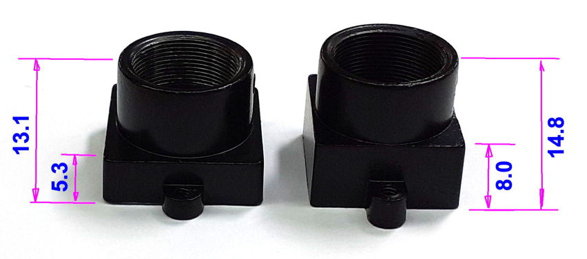
We are now naming our operating system SD cards with the letter "P", so we have P3034B as the 24MAR20 32-Bit Stretch platform, and we now have P3034C as the up-coming 32-Bit Bullseye platform, which will support the RevD camera and use the libcamera library.
[11-JUN-22] The libcamera libraries support rotations of 0°, 90°, 180°, and 270°. But the Rasbperry Pi implementation of libcamera for libcamera-vid provide only 0° and 180°, as well as vflip and hflip, but no combination of these provides 90° or 270°. But ffmpeg will perform any manipulation we like. We run an existing video through ffmpeg H264 compression and record ffmpeg's value for compression "speed", which is inversely proportional to the time taken to compress and rotate the video.
| Manipulation | Speed | Command |
|---|---|---|
| none | ×35.6 | ffmpeg -i in.mp4 -c:v libx264 -preset veryfast Out0.mp4 |
| 90° clockwise | ×36.3 | ffmpeg -i in.mp4 -c:v libx264 -preset veryfast -vf "transpose=clock" Out90.mp4 |
| 180° clockwise | ×35.0 | ffmpeg -i in.mp4 -c:v libx264 -preset veryfast -vf "transpose=clock,transpose=clock" Out180.mp4 |
| 270° clockwise | ×33.2 | ffmpeg -i in.mp4 -c:v libx264 -preset veryfast -vf "transpose=cclock" Out270.mp4 |
| 270° clockwise | ×32.7 | ffmpeg -i in.mp4 -c:v libx264 -preset veryfast -vf "transpose=clock,transpose=clock,transpose=clock" Out270.mp4 |
| none | ×32.8 | ffmpeg -i in.mp4 -c:v libx264 -preset veryfast Out0.mp4 |
Image rotation does not appear to cause any significant increase in the computational difficulty of the compression. We should be able to move the rotation out of the libcamera-vid call and into our compressors.
[13-JUN-22] We are able to get MPlayer to rotate live video display by +90° and +270° using -vf rotate=n, where n is 1 for 90° clockwise and 2 for 270° clockwise. If we want 0° or 180° with the Bullseye platform, we perform the inversion at the source, in libcamera-vid.
[14-JUN-22] We use a combination of libcamera-vid and mplayer to support all four rotations of the image during live view from Bullseye, and a combination of libcamera-vid and ffmpeg to support them during recording on Bullseye. The recording view is a view of the recorded video, so it's taken care of also. We have a Raspberry Pi 4B 2GByte. We insert our 32-Bit Bullseye SD card, plug in a RevD camera, connect a USB-C power adaptor, and boot up. We record video for several minutes and all goes well. Lag is 4 s, CPU gets to 60C clock speed starts at 1.8 GHz and ends at 1.8 GHz.
[04-JAN-23] We are performing quality control on eleven A3034C equipped with P3034B (24MAR20 32-Bit Stretch) and UC350 Rev C cameras. We note that some cameras give better color balance in daylight than others.
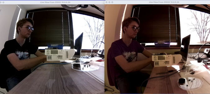
We try the cameras in the dark with infra-red light. The cameras that give good color balance in daylight cannot see infra-red. They are equipped with infra-red blocking filters over their image sensors. We try to remove the filters, but the filter glass shatters and we damage the image sensor. We have no more UC-350 Rev C sensor boards. We have ten UC-350 Rev D sensor boards, five of which we now realise are equipped with infra-red blocking filters. The other five we can use to replace UC-350 Rev C with IR-block, but only after we upgrade the operating system of the Pi to P3034C (09JUN22 32-Bit Bullseye).
[05-JAN-23] We set up our SDBurner Raspberry Pi 3B with graphics, wifi, and wired Ethernet. We clone our P3034C_09JUN22 (32-Bit Bullseye) master SD card, storing as sparse file P3034C_09JUN22.img on the SDBurner main drive. We copy the image onto a 16GB and a 32GB SD card. We use the master copy to boot up a 3B+ with RevD camera. We try out Videoarchiver 27 with the ACC and encounter several problems. The program freezes when we try to reboot the ACC. The program cannot set the lights on the ACC. We fix both of these in Videoarchiver 28. Live image streaming as well as recording to disk, updating firmware on the ACC, and querying all work. But the images are red-tinted and it takes ten seconds to get streaming to start.
[06-JAN-23] We use "libcamera-hello --list-cameras" to see the list of supported modes for the RevD camera on our P3034C system and get the following.
0 : imx219 [3280x2464] (/base/soc/i2c0mux/i2c@1/imx219@10)
    Modes: 'SRGGB10_CSI2P' : 640x480 1640x1232 1920x1080 3280x2464
           'SRGGB8' : 640x480 1640x1232 1920x1080 3280x2464
We play around with the "--awbgains r,b", "--mode w:h", "--width w", "--height h", and "--awb word" options. These do not interact in any way we find easy to summarise. The combination "--mode 1640:1232 --width 820 --height 616", as does "--mode 1640:1232 --width 1640 --height 1232". We cannot get the stream to drop resolution down the 410×308.
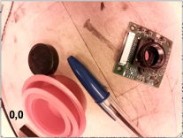
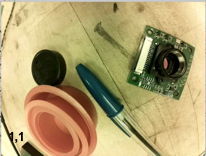
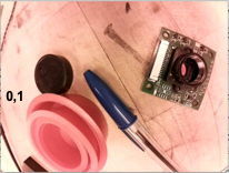
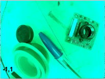
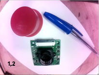
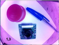
[20-JAN-23] We work with Y61029. It is running fine. We disconnect power, later connect to a LWDAQ cable by mistake, and after that, the Ethernet interface does not work. We get PoE and the Pi boots up, but no link light. This symptom we have observed before, and is currently being exhibited by a camera in Paris. Assign names A3034C1 to RevC with Stretch and A3034C2 for RevD with Bullseye. We equip Videoarchiver V28 with detection of the two internal camera connection errors we are encountering with the A3034C2: "failed to connect to camera" and "no camera found". We read the stream log file occasionally to check for these phrases and recommend the user reboot until live view works. During recording, if we encounter these errors, we find that the existing restart-recording algorithm resolves the problem thirty or sixty seconds later.
We remove our Automatic White Balance scheme for improving the A3042C2 color balance. We use instead a color calibration table as described and recommended here. So far as we can tell, the table compensates for color changes introduced by wide angle lenses interacting with the window over the image sensor. We download imx219_200.json from here and paste it into a script entry in the Videoarchiver V28 data section. When we update firmware, we write this table to colors.json in the ACC's Videoarchiver directory.
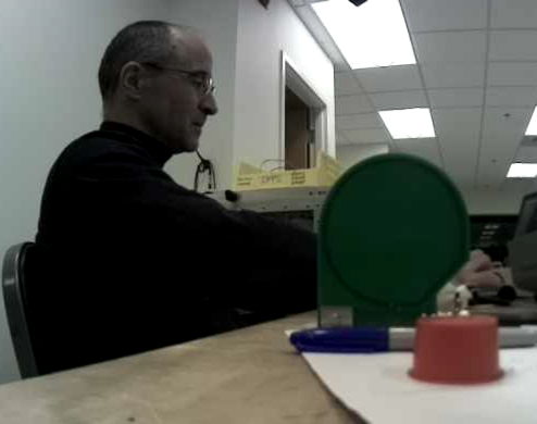
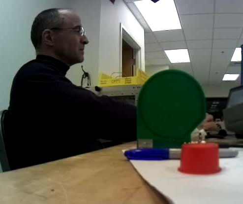
We update our existing six A3034C2s with Videoarchiver V28. We record one-minute videos from four of them for twenty minutes, all is well. Monitor display working well as we switch between cameras. We believe we now have 6 of A3034C1 and 6 of A3034C2 that are ready to ship. We continue exercising the cameras. We record from three cameras with their lens caps on and find that these fall behind in their compression, so that they are lagging by 30 s after about five minutes. Another with cap off lags by 4 s. Remove caps, the three lagging cameras catch up. When the caps are on, the images we obtain are dim and blurred. After running for half an hour, pointed at us assembling and gluing, the four cameras have reached thermal equillibrium at 54-56 °C. Ambient temperature is 24°C.
[21-JAN-23] We double the scaling of the saturation value for C2 cameras in the Videoarchiver. Now a value of 0.5 gives bright colors. New take new sets of Exposure Compensation and Color Saturation example images and are well-pleased with the results, see 0.0, 0.2, 0.4, 0.5, 0.7, 1.0.
[23-JAN-23] We have P0139, an A3034C1, back from Paris. The Ethernet interface on the Pi 3B+ is not providing a link. We replace the 3B+ and all is well. We update firmware, run with Videoarchiver 28 and scheduler. Check white and infrared lights. Record from P0139 along with Y61030, an A3034C2. One-minute videos from the C1 camera are 2.2 MByte while those from C2 are 5.8 MBytes. The C1's one-second segments are about 50 kBytes, while the C2 two-second segments are about 200 kBytes. We improve the focus of the C1 camera, but this makes no difference. We set the constant rate factor for the C2 to 31, while for C1 we leave at 23. Now the one-minute videos are 1.6 MByte for C2. We try 27 and now the C1 is 2.2 MB while C2 is 2.9 MB. We watch slowa and rapid hand movement in the recorded video. We cannot see any significant difference in the quality of the video. Both cameras are settling at 54 °C.
[24-JAN-23] We record from thirteen cameras, seven A3034C1 and six A3034C2. Recording is stable with transfer period 60 s and video length 600 s. But with transfer period 10 s and video length 60 s, our MacBook Air cannot keep up with video concatination. Recording lags and stalls. We turn on the lamp scheduler to cycle the lamps. Processor temperatures vary from 48°C to 54°C, with both C1 and C2 among the hottest. Lag 2-6 s. Lamp scheduling does not have a significant effect upon the lag. Verbose reporting, however, causes the lag to increase by several seconds per minute. We add to the Videoarchiver an automatic turn-off of verbose reporting when the lag exceeds the alarm length in any camera.
[01-FEB-23] Documentation of the original raspivid camera library has disappeared from the Internet. The manual page used to be here.
[21-FEB-23] We are working on the synchronization of twenty-four hour videos that we create with the Neurplayer's Exporter. We are watching the length of the segments we download from an A3034C1 and an A3034C2. In both cases we are using two-second segments. We find that the length of the segments is unreliable immediately after we synchronize the camera clock. We add a separate synchronization timer to the Videoarchiver, and let this be ten minutes by default. We find that the camera occasionally drops a few frames from a forty-frame segment when there is no movement whatsoever in the field of view. We stop using the segment timestamps to determine the length of our recording files, but instead count the number of segments we have accumulated, because the segments appear to be 2.00±0.05 s long, while the timestamps in the file names can deviate from the 2-s period by ±1 s, although they never overlap. We check both our cameras with timedatectl. Both claim that their NTP service is inactive. The only synchronization these cameras receive is from the Videoarchiver. The Raspberry Pi clock we trust to be stable to accurate to ±20 ppm, which is 72 ms/hr. So we set the default synchronization period to one hour. We enhance the Videoarchiver to add blank frames to the end of a segment when it is too short, and to curtail the segment if it is too long. We set too long as 105% and too short as 95% of a segment using min_seg_frac = 0.95.
[12-MAR-23] Streaming video with our new Videoplayer tool, we find that the C1 camera running raspivid drops up to half the frames when there is no movement or change in the field of view. The C2 camera drops no frames when streaming.
[13-MAR-23] We replace MPlayer with our own Videoplayer in Videoarchiver 31. We look at compressed video in the recording view and are not satisfied with crf=27 for C2 cameras. We restore the default crf for C2 back to 23. We record from a C1 and a C2 on our bench next to one another while we work in front of them. After an hour, the C1 is at 55°C and the C2 is at 57°C. Ambient temperature on the bench is 24°C. Images are sharp. Camera clock speeds are 1.4 GHz steady. Lag time is 3 s for the C1 and 4 s for the C2. We are using two-second segments for both.
[15-MAR-23] Videoarchiver 31 running on MacOS, Windows, and Linux in LWDAQ 10.5.4. We are building another ten A3034C2 cameras. When reading with Videoarchiver 31 we are scaling live and monitor video by 0.5 on Linux and Windows to reduce data rate through the Videoplayer pipe, then zooming by 2 to restore the size of the window. We are having no start-up problems with the cameras when contacting them from Windows.
[28-MAR-23] We compare the colors we obtain from the A3034C1 and the A3034C2. We are able to build C1s because we just received five UC-350 Rev C sensors. We compare the color balance provided by the UC-350 Rev C with raspivid interface (Raspbian Stretch) and the UC-350 Rev D with libcamera interface (Raspbian Bullseye).
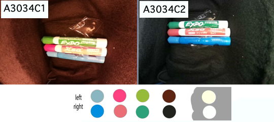
We put our A3034C1 and A3034C2 in a black box with white LEDs turned on. The color balance is superior in the C2 version. We order 20 of the UC-350 Rev D direct from the manufacturer UCTronics. Our biggest concern with the C2 version is its tendancy to fail to start streaming. But it seems that this problem arises only on MacOS, for reasons we do not understand. On Windows 11, we start and stop live streaming ten times on two C1 and four C2 cameras, and we start recording five times. We see no startup errors.
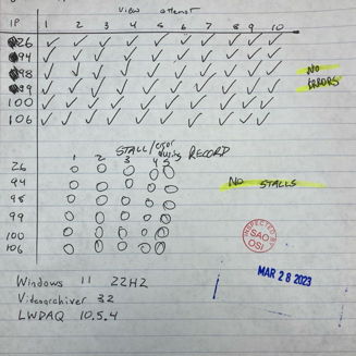
[29-MAR-23] We load two UC-350 Rev C sensor board into ACCs with Raspbian Bullseye. They all work fine. We have a year-old A3034C1 with an older UC-350 Rev C sensor board. We load that ACC with Raspbian Bullseye. It works fine. We will proced with construction of A3034C2 using either Rev C or Rev D cameras, all with no IR-block filter (they are NOIR). The Rev D cameras do not work with Raspbian Stretch. But the Rev C cameras work with both Stretch and Bullseye.
[13-APR-23] We have 23 hours of video from an A3034C1 (Y61026) and several A3034C2. We concatinate the entire 23 hours into one video using the Neuroplayer's Exporter. The original video is in 600-s segments. The Exporter pads segments that are shorter than 600 s and clips those that are longer. It measures length by counting frames and dividing by twenty frames per second. The C1 segments always need clipping or padding. At best, they need four frames clipped. At worste, they need several thousand frames added. The C2 segments never need more than one frame added or one frame clipped.
[29-NOV-23] We receive twenty new Pi 3B+ boards. We note that our Stretch OS will not boot on these boards, while our Bullseye OS boots as usual. We find this report of the same problem. It appears that we can hack our Stretch OS so it will boot on these new boards, should this prove necessary. In the meantime, we still have one A3034B operational.
[13-DEC-23] We find that the DSL227D lens, with slightly shorter thread, fits just as well as the DSL227A in our holder, so we order these instead because they are in stock at Sunex. We are making ten more A3034C2-A. The first one is Y710254. We place it on our bench and run. After one hour, CPU temperature is 55°C.
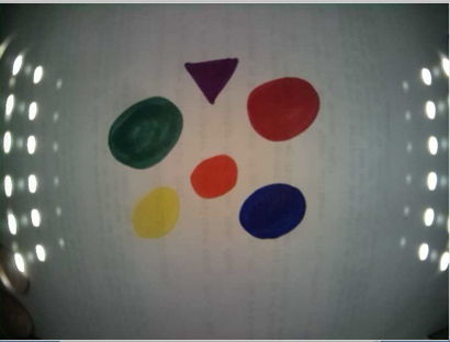
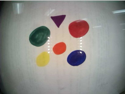
[21-DEC-23] We have ten new A3034C2-A cameras. They have burned in for forty-eight hours, recording continuously, sitting six inches apart, long side down on a wood table. Ambient temperature is 24°C. The camera temperature sensors report 54.2-57.8°C, which is 30-34°C above ambient.
Y71022  54.2
Y71023 54.2
Y71024 53.7
Y71025 52.1
Y71026 54.8
Y71027 57.8
Y71028 52.6
Y71029 55.8
Y71033 55.8
Y71035 54.2
During the fourty-eight hours, we cycled the white and infrared lamps alternately every hour. We checked recordings from all cameras to make sure we can see the infrared light at night. All perfect.
[15-MAR-24] We attempt to improve our color calibration, which is encoded in a manner we do not understand in the Cr, Cb, and lut tables of our color.json file. In principle these are YCC color encodings, but when we assign our own arrays of values, the colors do not respond in a manner we can decypher. Nevertheless, we proceed with an investigation. We prepare the 16×12 arrays of Cr, Cb, and Y calibration values with this script.
set pedestal 0.5
set efactor 0.5
set esigma 50
set pdiv 400
set of [open ~/Desktop/calib.txt w]
for {set j -5.5} {$j <= 5.5} {set j [expr $j + 1]} {
	for {set i -7.5} {$i <= 7.5} {set i [expr $i + 1]} {
		set value [expr $pedestal+$efactor*exp(-($i*$i+$j*$j)/$esigma)]
		set value [expr $value+($i*$i+$j*$j)/$pdiv]
		puts -nonewline $of "[format %.3f $value], "
	}
	puts $of ""
}
close $of
The script writes an array to calib.txt, which we cut and paste into the Videoarchiver.tcl script in place of Cr, Cb, or Y. The array consists of a pedestal, a gaussian, and a scaled parabola. We focus our camera lense, DSL227D, and place a white card 7 cm from the lens. We turn on the white LEDs to power level 8. We want to see the card as white or uniform gray. After forty or fifty trials, we arrive at 0.5, 0.5, 50, 400 to generate Cb, 0.5, 0.5, 100, 200 to generate Cr, and 1.0, −0.5, 50, ∞ to generate Y.

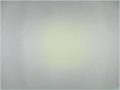
Here are two examples of the libcamera YCC implementation, neither of which we understand. In Test 14, we have to top and bottom half of the Cr, Cb, and Y array taking values 0.5/2.0, 2.0/0.5, and 2.0/0.5 respective. In Test 15 we have 0.5/2.0, 2.0/0.5, and 0.5/2.0. The Y is supposed to be luminescence, and we expect from our reading of the YCC definition, that Y will not affect color. But it does affect color.

Our arrival at a solution for the color calibration was empirical. We are confident it is not a unique solution because we observe that scaling the values in one of the tables by a factor greater than zero appears to have no affect upon the appearance of the image. When we return to the Arducam json library here, we find these files are no longer compatible with our libcamera, although we can cut and paste the Cr, Cb, and Y arrays into our own json. The Arducam file for 160° is the same as the one for 120°. None of the files are radially symmetric.
[01-APR-24] We check the synchronization on our Y71049 camera and find the delay to be −2.6 s since Friday. We set up five of A3034C2 with three TCBs, all recording on a Linux machine from our Faraday canopy. After running for the weekend, we compare video and telemetry and find the Y71036 video is delayed by roughly twelve seconds, while the Y71044 video is delayed by six seconds. All video files are exactly 600 s with 1200 frames. Camera clocks are corrct to within a few tens of milliseconds. We examine Videoarchiver 36, and note that we are incrementing the file time stamp by a fixed number of seconds: the requested length of the recording file. Our segements are nominally 2 s long. If the cameras produce fewer than 38 frames in a segment, we pad to 40 frames. If the cameras produce more than 42 frames in a segment, we clip back to 40 frames. But the segments are at least 39 and at most 41 frames in every case. Recording 2-s segments we see a correlation between segment length and segment timestamp. If the segment length is 2.00 s, the timestamp of the next segment is 2 s greater. If the segment length is 1.95 s, the timestamp can be only 1 s greater. The segment after that will usually be 3 s greater, so that the average segment length is 2 s. We call the 1-s displacement of the timestamp the edge effect.
We are synchronizing the camera clocks every hour, which seems to keep them within ±200 ms. But the synchronization does not stop the camera clock running at a different speed from the computer clock, and the frame rate is dictated by the camera clock. Eventually, we will have a 1-s step in segment timestamp that is not followed by a 3-s step. Or we will have a 3-s step not followed by 1-s step. The names of the segments give us their start time to ±200 ms, with the exception of a few that are off by 1 s either way due to edge effects. Videoarchiver 36 was incrementing the recording file timestamps by a fixed record_length_s. Eventually the timestamps are off. Twelve seconds in three days is 46 ppm, which would give us a drift of 170 ms/hr. We are inclinded, therefore, to use the timestamp of the first segment of a each new video as the video timestamp. But there is a 10% chance that the edge effect will offset this timestamp by 1 s.
[02-APR-24] We ran overnight using segment timestamps for recording files and check synchronization this morning, both cameras good to ±200 ms. We have stopped the drift. We point five cameras at our enclosure, update Videoarchiver to include some further edits, but no significant changes, and start recording again. We would like a more robust way to pick the timestamp of each video file, rather than just picking the timestamp of the first segment. For each new recording file, we assemble a list of points (x,y) made out of the time offset from the first segment and the segment index. The ideal sequence will be (0,0), (1,s), (2,2s), ... where s is the segment length. We fit a straight line to these, find the intercept on the y-axis, round the intercept, and add this value to the first segment timestamp to obtain our recording file timestamp.

In the plot above we show how the residuals from a straight line fit might look, choosing two extreme cases. In F1, half the segments disagree with the other half. Our intercept is −0.54 s. We would round to −1. In F2, one segment is misplaced and has hardly any affect upon the intercept. We implement the intercept timestamp algorithm in Videoarchiver 37.
[04-APR-04] Synchronization today is good to ±100 ms. No problems with the new Videoarchiver with its intercept timestamp algorithm. Cameras CPUs are at equillibrium 47.8-49.4°C with ambient 22.8°C, roughly 26°C above ambient.
[16-MAY-24] We have seven cameras, most of which rattle when we shake them. We open them up and find that it is the shields on the 5-V, 10-W DC-DC converters that are rattling. We make some effort to secure them in place. We re-assemble and measure equillibrium temperature while recording from a person moving at their work bench. Two still rattle when we shake them.
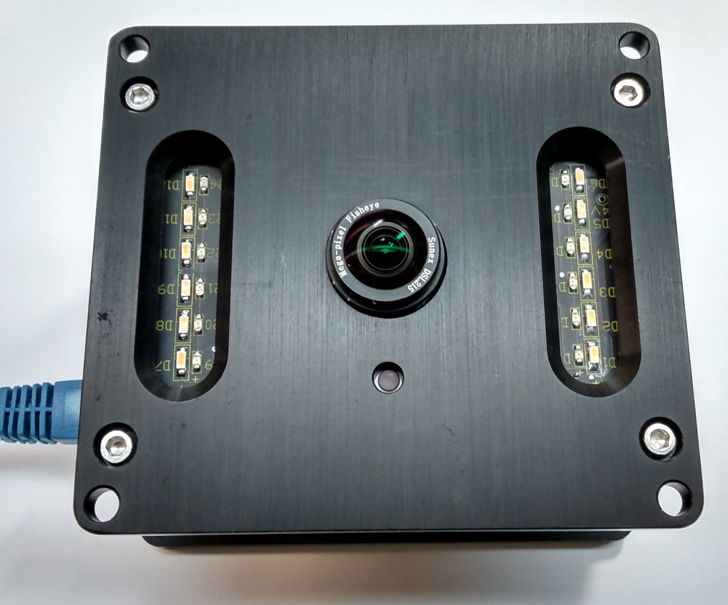
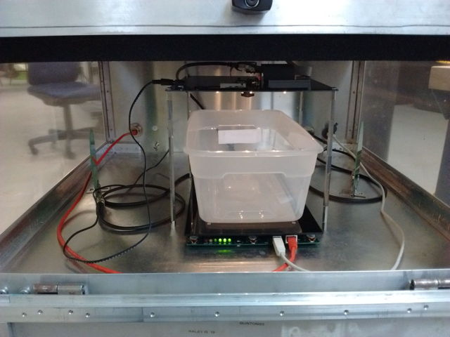
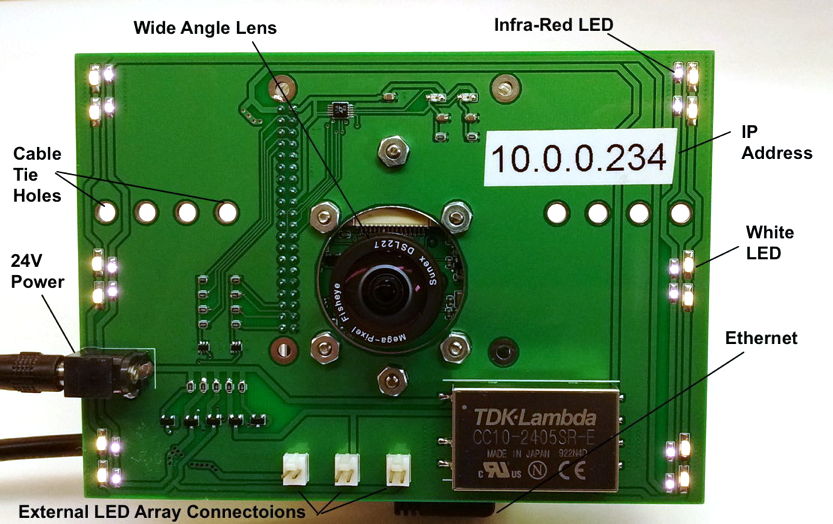
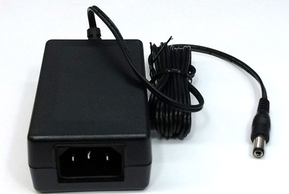
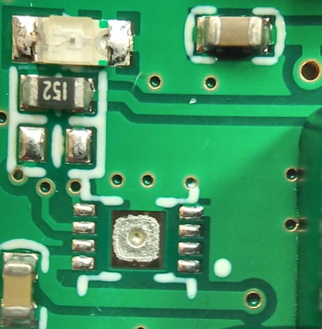