We use a live video display when we adjust the picture acquired by each camera. Each camera has its own View button to display what it sees. When we are not recording from a camera, the view is an un-compressed stream that shows up on your computer screen. The state of the camera will be shown as "Live". The delay between movement in the field of view of the camera movement will be barely noticeable to the human eye. We use the live display to determine the effect of illumination, adjust the focus of the camera, and make sure we have no distracting reflections in the field of view. Once we are satisfied with the picture obtained from the camera, we can start recording. We start recording with the Record button. Our live display will close and recording to disk will start up.
During recording, the un-compressed video stream is not downloaded by the data acuisition computer. Instead, the stream is stored temporarily within the camera, broken into consecutive segments of length one or two seconds. Each segment is namaed after its start time in Unix seconds. The camera compresses these segments, reducing their size by a factor of ten with no appreciable loss in image quality. It is these one-second compressed segments that the Videoarchiver downloads to the data acquisition computer. The delay between movement in the field of view and the arrival of compressed video in the data acquisition computer is the recording lag. The Videoarchiver displays the recording lag in units of seconds on the right side of each camera's control bar. If we press the View button during recording, the Videoarchiver will display the incoming compressed segments. The display will be delayed by recording lag, and the display will flicker every second as a new segment is loaded into the video player. If we move or change the size of the recording view, the display resets its position and size every second. The recording closes itself automatically after monitor_longevity seconds. If we leave the monitor view open, it tends to freeze after ten or twenty minutes. Just press View to open it again.
By default, the Videoarchiver adds new segments to its video recording file once every sixty seconds, and every ten minutes it creates a new recording file. We must refrain from viewing the recorded files why they are being built by the Videoarchvier. Doing so can cause the Videoarchiver to stall. We can turn on and off the white and infrared lamps of individual cameras using their individual control buttons. We can turn off all the lamps with a single press of Lamps_Off. And we can set up a schedule for turning on and off the lamps of all cameras with the Scheduler.
Download and decompress the zip file. The result is the Videoarchiver directory. Place the Videoarchiver directory next to your LWDAQ directory. Having followed our Animal Cage Camera set-up instructions, the Videoarchiver should be able to communicate with your camera. The cameras and the data acquistion computer will be connected to the same Power-over-Ethernet (PoE) switch, forming a local Ethernet. When we first open the Videoarchiver, we will be presented with a camera list consisting of only one camera, as shown above. We enter the IP address of one of our cameras in the IP entry box. When we ship a camera, its IP address will be 10.0.0.X, where X is the last three digits of the serial number, with leading zeros dropped. You can always reset the IP address of a camera to a universal default value of 10.0.0.34 by with the help of the camera's configuration switch. Assuming we know the IP address of a camera, we can change that IP address with the Videoarchiver's IP button. We can check communication with a camera at any time, and identify which of several we are communicating with, by turning on its white LEDs. We select "15" from the White LED menu button and the LEDs on a camera will turn on, or we will see a timeout error in the Videoarchiver text window.
We specify the quality of the compression with the "constant rate factor" or "crf", used by the H264 compression algorithm to control the extent to which moving objects will be blurred in the compressed video. At crf=1, there is no blurring at all, and at crf=51, all movement and edges in the picture are blurry. The standard value for high-quality compression is crf=23, and this is the value we use for our higher-resolution video. When we choose lower-resolution, we increase the compression quality still further with crf=15 so that we can see every pixel in the video output, and we can take advantage of the higher frame rate the lower-resolution vicdeo provides.
The Videoarchiver's recording process is designed to provide continuous, clock-synchronized recording of video to disk. It is not designed to provide simultaneous viewing of video during recording. Nevertheless, if we press the View button during recording, the Videoarchiver will open a recording monitor window that will display a delayed version of the video being produced by the camera. The delay will be four or five seconds, and is the time it takes the camera to compress a video segment, and for the Videoarchiver to download and write the segment to disk. The recording view operates for only one camera at a time. We can press the View buttons of consecutive cameras and have the recording view switch between them. We recommend you close the recording view when you are done with it. The fewer processes the Videoarchiver has to manage, the more reliable it will be.
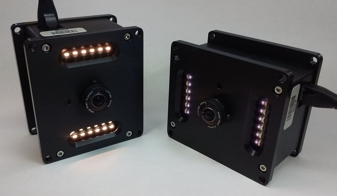
Figure: Two Animal Cage Cameras (A3034B). Left: white LEDs on dim. Right: infrared LEDs on full power, seen through the infrared blocking filter of our mobile phone camera.
If we unplug a camera during recording, the Videoarchiver will attempt to re-start recording restart_wait_s seconds later. Any time communication with a camera takes longer than connection_timeout_s seconds, the Videoarchiver will assume that the camera needs to be re-started. When recording is interrupted, we say it is stalled, and the Videoarchiver marks the state of the camera as "Stalled". The default restart wait is 30 s, and the connection timeout is 5 s. We can view and adjust these parameter, and other Videoarchiver parameters, in the Configuration Panel, which we open with the Configure button.

Figure: The Videoarchiver Configuration Panel.
The Videoarchiver keeps a log of all the times a camera stalls, and all the times it is able to re-start recording, as well as all errors and warnings issued by the Videoarchiver. We can view this log with the View_Error_Log, and clear the log with the Clear_Error_Log. The Save Configuration button saves the Videoarchiver parameters, but does not save the camera list. The Unsave Configuration button is useful for removing a configuration you don't want any more. Re-open the Videoarchiver after pressing the un-save button, and you will be back to the default settings.
The Q button provided for each camera queries the camera for its log files, and prints them out to the text window. We can use these log files to track down problems with compression and communication. The R button allows us to reboot the camera without disconnecting its power. The U button causes the Videoarchiver to update the camera's firmware. If you see errors that are not timeout errors when you communicate with a camera, it could be that the camera firmware needs to be updated to be compatible with your version of the Videoarchiver. In that case, press the U button. The updated takes less than ten seconds and does not require a re-boot.
We construct a new camera list with the Add_Camera button. We can delete cameras from a list with the X button at the end of each list entry. We can save and load lists to and from disk. The lists are saved as text files containing a sequence of Tcl commands that configure the Videoarchiver's internal camera list. When we open the Videoarchiver, it does not load a camera list automatically. We must load the list with the Load_List button, having previously saved it with the Save_List button. You can save any number of different camera lists, but if you want to load a particular camera list when you open the Videoarchiver, make sure cam_list_file in the Configuration Panel points to your camera list, and press the Save to save the Videoarchiver configuration.
We turn on and off the camera's built-in white and infrared illumination with the Wht and IR buttons. We can set them to any of sixteen power levels zero to fifteen, where zero is off and fifteen is full-power. When we use these buttons, the lamps respond immediately. If we want to adjust the lamps gradually, we use the Scheduler, which allows us to define a regular schedule of lamp adjustment, and to specify how slowly the lamps should be adjusted. When we save our cameras list to disk, our schedules are saved along with the list.
Time Synchronization
The files recorded to disk are H264-compressed videos stored within mp4-containers. The files are saved in a subdirectory of the master directory. You specify the master directory yourself, but the Videoarchiver creates the subdirectories itself. If the directories exist, it re-uses them. There is one subdirectory for each camera, and they are named the same as the camera name in the Videoarchiver camera list.
The video files are named in the format Vx.mp4, where the x is a ten-digit Unix time. The first frame of the video was generated by the camera at the start of this Unix time, as reported by the clock on the data acquisition computer. Video file V1525694641.mp4 has Unix time 1525694641, which is "Mon May 07 08:04:01 EDT 2018". The video contains twenty frames per second. Its first frame was generated some time between zero and one twentieth of a second after the start of Unix second 1525694641. Because the videos are time-stamped in this way, and the frames within the video are arriving at a constant rate, we can navigate to a particular time within a video by counting frames. The time defined by the video file is what we call video time.
We also have computer time, which is the time on the data acquisition computer clock. The computer time may or may not be kept accurate by an network time server. Whether the computer clock is accurate or not, it is what we use to set the time on the camera clocks, and it is the camera clock that dictates the segmentation of video at one-second boundaries and assigns the Unix time of the segment name. The Videoarchiver attempts to keep all the camera clocks synchronized with the computer clock to within ±25 ms. It does this by correcting the camera clock by a few tens of milliseconds every time it starts a new recoding file. With record_length_s set to 600, this correction will take place every ten minutes, and each video file has length six hundred video-time seconds.
Meanwhile, we might be recording biometric signals with SCTs and an Octal Data Receiver (ODR). The ODR has its own temperature-compensated clock that keeps time to ±1 ppm. The Neurorecorder records biometric signals in NDF file that are time-stamped in the same way as the video files. The default Neurorecorder output file is in the format Mx.ndf, where x is the Unix second that began immediately before the first sample recorded in the NDF file. Because the NDF recordings contain clock messages from the ODR, we can navigate to a particular time within an NDF by counting clock messages. The time defined by the video file is what we call signal time.
The computers used to record video and telemetry from laboratory animals are not usually connected to the internet at large, and so do not have access to a network time server. A computer clock left to run without network correction will, in our experience, drift by ±1 s/day, or 10 ppm. The ODR clock is ten times more accurate than most computer clocks. We might think to correct the computer clock using the ODR clock. But correcting a computer clock is a delicate business. When we move the clock backwards, some actions that have already taken place will be presumed not to have taken place, and will be repeated. When we move the clock forwards, some actions that have not taken place will be presumed to have taken place, and will be skipped. When a computer adjusts its time to match a network, it does so by slowly speeding up or slowing down. Even if we were willing to embark upon the development of such a synchronization algorithm for the data acquisition computer, what would we do when we wanted the computer synchronized with respect to absolute time with the help of a network server? And in any case, even a 1 ppm drift is 100 ms per day, and after a year, this amounts to half a minute. Even the ODR clock will be wrong by a significant amount eventually. If our objective is to synchronize our recordings to an absolute universal time, we must have access to a network time server. But that is not our objective.
Our objective is to synchronize signal time with video time so that we can view signals and video simultaneously in the Neuroplayer, and be sure that the two are simultaneous to within ±50 ms. It does not matter to us that the computer time is wrong, so long as video time and signal time are synchronized with one another. Our strategy is to synchronize both video time and signal time with computer time. As we have already mentioned, we synchronize the signal time on the camera clocks every ten minutes by default. The Neurorecorder, meanwhile, by default records one-hour NDF files, as measured by counting ODR clock messages. When the Neurorecorder has received exactly one signal-time hour of data, it stops recording and waits until the start of the next second of the computer clock. When the new second begins, the Neurorecorder immediately resets the ODR clock and begins recording another signal-time hour of data, naming the new NDF file after the new second. If the computer clock is a fraction of a second faster than the ODR clock after one hour, this process results in a minimal loss of data. But if the computer clock is a fraction of a second slower, we will lose up to one second of data every hour, and consecutive NDF file timestamps will differ by 3601 s instead of 3600 s.
During the recording process, the ACC is recording its own live, uncompressed video stream in one-second time-stamped segment files. It is also running several parallel compression processes that read in the un-compressed segments and produce compressed one-second segements. The first frame of each compressed segment is a key frame containing the full image. The Videoarchiver queries each camera frequently. As soon as a new compressed segment becomes available, the Videoarchiver downloads the segment to the data acquisition computer and deletes the segment from the camera. Every transfer_period_s, the Videoarchiver adds the new segments to its existing video file, until the file is record_length_s long, at which point the Videoarchiver starts a new video file. The video files created by the Videoarchiver contain a key frame every second, so we can navigate quickly and accurately to any one-second boundary within the video.
Example: The video file V1525694641.mp4 is exactly one minute long. It was constructed out of 1-s segments. It contains a key frame at the start of every second of video time. The time on the phone clock at the beginning is 08:04:01 and at the end is 08:05:01. The file itself is 7.4 MBytes, or 120 kBytes/s.
When we are viewing video and signals in the Videoarchiver, we must use a playback interval length that is a multiple of one second, or else the video time navigation will be inaccurate and slow. In order to get to a half-second video time, the video player would have to find a key frame preceeding the half-second time, and play the video until the half-second time to reconstruct the image at the intermediate moment, then stop. While it is doing this, it either displays the unwanted video, or it displays a flat color. Neither behavior makes for easy viewing, so the Neuroplayer prohibits video playback with playback intervals shorter than one second.
File Sizes
To investigate the effect of resolution and frame rate upon recording file size, we set up an ACC to record video of one or two people moving about on a couch, in an attempt to simulate a close-up view of animals in a cage. The following table give measured values network bandwidth required to live stream un-compressed video from the camera, and the size of the video when compressed with our standard compression quality.
| Live Streaming | Bandwidth
(MBit/s) | H264 Compressed Size
(MByte/min) |
|---|
| 410 X 308 at 20 fps | 5 | 1.1 |
| 410 X 308 at 40 fps | 11 | 1.1 |
| 820 X 616 at 20 fps | 15 | 3.1 |
| 820 X 616 at 40 fps | 17 | 3.8 |
| 1640 X 1232 at 10 fps | 16 | 23 |
| 1640 X 1232 at 20 fps | 18 | 26 |
Table: Live Streaming Bandwidth and Compressed Video Size for Various Video Resolution Settings. When live-streaming, the ACC transmits individual frames compressed with JPEG, but with no inter-frame compression. The compressed video is produced by the H264 algorithm with crf=23.
The compressed video size does not increase in proportion to frame rate. The H264 compression carries information from one frame to the next, so that each new frame is a list of modifications to the previous frame, rather than a new presentation of an entire frame. When we navigate within a video, we move first to a key frame, and then play forward. The ACC video files have key frames at every one-secod boundary of video time, and by synchronization, these one-second boundaries are simultaneous with Neurorecorder signal time to ±50 ms
The record_length_s parameter sets the length of the recorded video files. When we add new segmets to the end of a video file, the process is not as simple as adding new data to an NDF file. We cannot simply write the new file on to the end of the old file. Instead, we must read the existing file into memory, followed by the new segments, and concatinate them to create a new, self-consistent video file. We use this to replace the original file. The longer the video file becomes, the more effort we must spend to extend it with new segments. On the other hand, the shorter the video files, the larger the number of files we have to deal with in our file system. We recommend that you leave the recording file length at 600 s, which is the default. This length limits the number of video files to six per hour, but at the same time avoids copying longer files. The length of time between segment transfers is also important. The longer we wait to transfer segments, the fewer times per hour we have to copy the video file.
Figure: Video Concatination Time versus Number of Segments Concatinated. Orange: Total concatination time with no adjustment for the size of the existing video file. Blue: Concatination time after adjusting for existing video size by subtracting 2.8 ms/MB. Platform: 1.1 GHz Quad-Core MacBook Air running MacOS 10.15. Slope of adjusted time is 7.4 ms/seg.
We recommend transfer_period_s of 60 s. The transfer process takes roughly one second with a five-minute long video file. If we are recording from ten cameras, the transfer time amounts to ten seconds. If we attempt to transfer every ten seconds, we will have no time for downloading segments. By transferring every sixty seconds, the transfer time is kept to less than 20% of the time available.
Exposure Compensation
The camera adjusts its exposure time automatically to suit the ambient illumination. We control how the camera chooses its exposure time, so as to favor bright or dark parts of the image with its exposure compensation value, shown as Exp in the controls for each camera. We can set this value between 0.0 and 1.0 with a drop-down menu to make the image darker and brighter respectively.
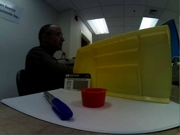
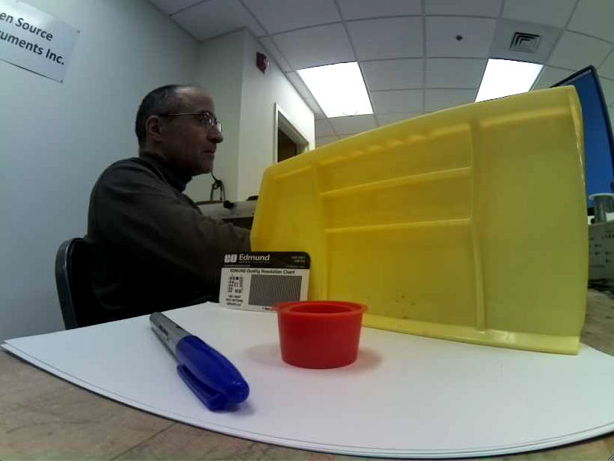
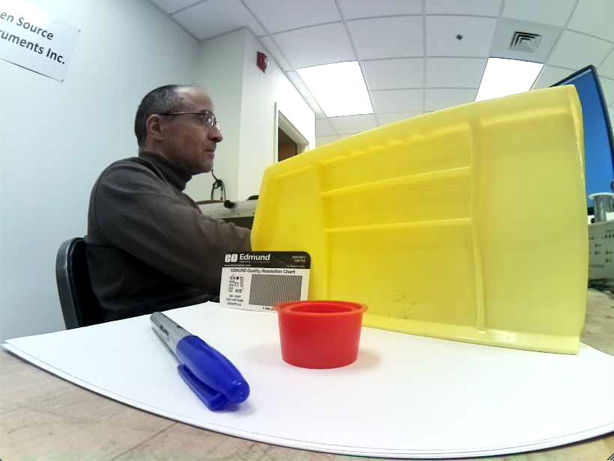
Figure: Exposure Compensation Adjustment in A3034C2 Camera. Exposure compensation values 0.0 (Left), 0.5 (Center), and 1.0 (Right). All with color saturation 0.5 in white LED lighting.
The exposure compensation value will be applied only when you start live capture or start recording. At other times, it will do nothing.
Color Saturation
In the Videoarchiver, set the Sat value to something between 0.0 and 1.0 to make the image more or less colorful. A value of 0.0 produces a black and white picture. A value of 1.0 produces an image that is, in our opinion, too colorful. The default value is 0.5, which is, in our opinion, just right. Adjust saturation before you start video streaming.
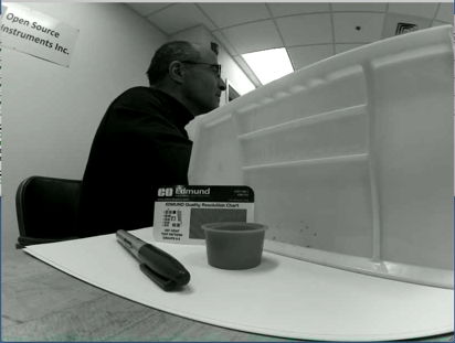
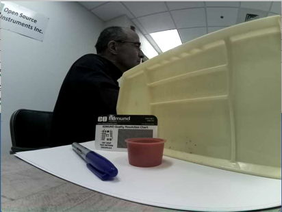
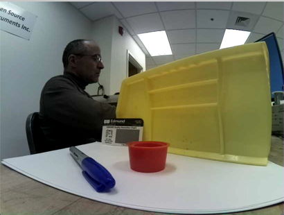
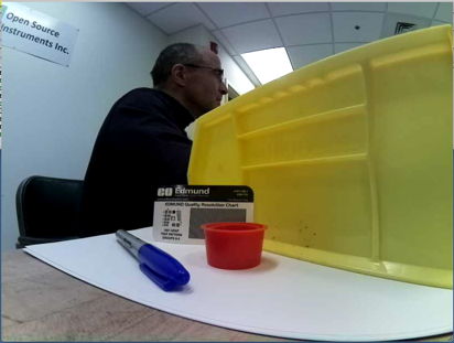
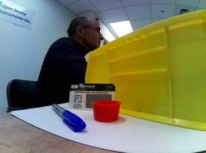
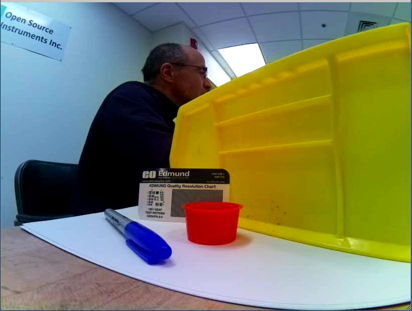
Figure: Color Saturation Values in A3034C2 Camera. Saturation values 0.0 (top-left), 0.4. 0.5. 0.7, and 1.0 (bottom-right). All taken with exposure compensation Exp = 0.5 in white, overhead LED lighting.
The ACC comes with a lens that has no infrared blocking filter. It can see in the light of its own infrared illumination, or its own white illumination. In a room with fluorescent and white LED lighting, the camera colors will be accurate, as in the photographs above. A mixture of infrared and white light disrupts the color fidelity of the image, as shown below.
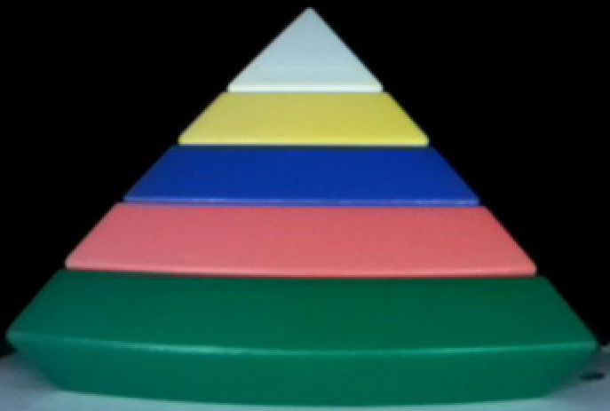


Figure: Images of Brightly-Colored Object in White LED Light (Left), Infrared LED Light (Center), and White Plus Infrared Light (Right). Click for higher-definition image.
By using only overhead LED lighting during the day, and only infrared light during the night, we obtain true color images during the day and gray-scale color images at night, without any need to adjust color saturation or exposure compensation as the lighting changes.
Color Balance
[15-MAR-24] When the color balance of a camera is perfect, a white card illuminated by the camera's white LEDs will be white or light-gray. When we update a camera with the Videoarchiver's update button, we deploy our latest color balance calibration.


Figure: White Card Images from A3034C2 in White LED Light. Left: Videoarchiver 33. Right: Videoarchiver 34.
In Videoarchiver 34, for example, we introduced a dramatic improvement in the color balance of A3034C2 cameras. Updating an A3034C2 camera with Videoarchiver 34 will transfer the new color balance to the camera.
Scheduler
[23-MAR-22] The Scheduler allows us to adjust the lamps on all cameras simultaneously according to a daily, weekly, or monthly schedule. Open the Scheduler Panel with the Scheduler button. When we save a camera list to disk, we also save our schedules, so they will be available the next time we open the Videoarchiver.
Figure: The Scheduler Panel. White lamps turn on at 07:15 each day, taking ten minutes to reach intensity level six. They turn off at 19:30, taking ten minutes to reach intensity zero. The infrared lights turn on at 19:30, taking 150 s to reach intensity 15. The infrared lights turn off at 07:25, taking 150 s to return to intensity zero.
The Scheduler uses the same schedule-definition syntax as the Linux cron utility. A schedule is defined by five fields: minute, hour, day of month, month, and day of week. A "*" for any of these fields means "ignore this field". Five stars means "never execute the task". A numerical entry in any field defines a time when the task should be executed. Days of the week are numbered 0-6 for Sunday to Saturday, but the Videoarchiver allows you to select the days by name in its menu button, then displays the number after you make your selection.
The Scheduler operates on all cameras at the same time. When it turns on the white lamps, it turns on all the white lamps. Whenever it adjusts the intensity of a lamp, it does so one intensity step at a time. To adjust from intensity zero to intensity fifteen requires fifteen steps. The Scheduler spends step seconds at each intensity level before moving to the next. If we set step to 10 s, the Scheduler will take 150 s to increase intensity from 0 to 15.
Design
Videoarchiver.tcl: The Videoarchiver Tool TclTk script, available in the LWDAQ/Tools/More folder.
Raspberry Pi: Home page for embedded Linux modules.
Camera V2: Manual for the Camera Module Version Two with IMX219 image sensor.
raspivid: The command-line utility provided by the Raspberri Pi to control the IMX219 image sensor.
ffmpeg: The video encoder we use generate video files.
Troubleshooting
[29-MAR-24] If you are having trouble with your video recordings, or with the Videoarchiver software, check the following list. Perhaps we have an answer prepared for you. If not, please register on the OSI Forum and create a new topic in the Video message board.
The Verbose checkbutton turns on additional reporting in the Videoarchiver's text window. We get to see the temperature of the microprocessor on the camera, the time taken to download each segment, and the time by which the incoming segments lag behind the local clock. This lag is an indication of how well compression is proceeding on the camera. If the camera is overheating, or activity in its field of view is excessive, it is possible that the camera will not be able to compress the video stream in real time. The lag should be between four and five seconds. If it is greater than ten seconds, or is increasing steadily, something is slowing down either the compression on the camera or the transfer of the compressed segments to the data acquisition computer. The Q button downloads and prints a set of log files from the camera. These files can offer clues as to what might be going wrong when video display or recording fails. The U button updates the firmware on the camera to match your version of the Videoarchiver.
Recording Stalled: The camera state is "Stalled" with a red background. Communication with the camera has been interrupted, or there is some internal error that is preventing video streaming. The Videoarchiver will reboot the camera and keep trying to connect until it succeeds. Best thing to do is wait for a few minutes to see if the Videoarchiver can fix the problem for you. If the camera remains stalled, stop recording and try other trouble-shooting steps.
Recording Produces No Video File: Use Q to look for errors. If you see an error message declaring that a file could not be found, stop recording and use U to uupdate the firmware on the camera. Try recording once again.
Compression Lagging: Use Q to check the ACC's processor temperature. If it's 60°C or greater, the processer will be slowing its clock to avoid over-heating, video compression will low down, and the lag between recording and transfer will keep increasing. The ACC is designed to operate between −10°C and +30°C while sitting on a flat surface, or −10°C and +35°C while held in the air by a camera mount.
Compression Lagging: If the microprocessor temperature is below 60°C, check the camera view. Did you leave the lense cap on? If so, the blurred images that result present the compression algorithms with serious difficulty because there are no uniform patches of color to compress easily. Remove the lens cap. Otherwise, is there excessive activity in the field of view? Perhaps a fan moving around, or many lights flashing? Reduce the activity in the field of view. The cameras can compress images of moving animals, but not images in which everything is moving.
Internal Camera Connection Failure: When you press View or Record you subsequently see a "failed to connect to camera" or "no camera found" error returned from the ACC. This is not a failure of communication between the Videoarchiver and the ACC. It is a failure of communication within the ACC. This problem occurs roughly 10% of the time you reboot a camera that uses the libcamera libraries, such as the A3034C2. It occurs less than 1% of the time when you reboot a camera that uses the older raspivid libraries, such as the A3034B1 and A3034C1. Try the View button a couple more times to see if the camera can configure itself without rebooting. If not, reboot with the R button. You may have to reboot more than once. Once the camera is running, it will continue to run.
Timeout Waiting for Socket Connection: When you press Q, the camera does not respond. Do you see an amber activity light flashing on the ACC's Ethernet socket? If not, check your connection to your PoE switch. Unplug and plug the cable. Do the white lights flash three times within thirty seconds? Is the amber light flashing? If not, you may have damaged the ACC's Ethernet interface by plugging a LWDAQ cable into its Ethernet socket. You will have to ship the camera back to us for repair.
Timeout Waiting for Socket Connection: When you press Q, the camera does not respond, but you have an amber link light flashing on the ACC's Ethernet socket. Check the IP address you are using with the camera. We ship with IP address 10.0.0.x, where x is the last two or three digits of the ACC serial number. If you continue to have socket connection failure, reboot while pressing the brown configuration button on the camera and try address 10.0.0.34. If you still cannot connect, check the network settings on your computer: you must configure your wired Ethernet connection to run on subnet 10.0.0, so that your computer will use its wired Ethernet to communcate with IP address 10.0.0.34. See here for instructions on configuring your wired Ethernet.
Poor Color Balance: Hold a white card in front of your camera with the white LEDs on to make sure that any non-uniformity in color is due to the camera. If you see uniform gray or white, the camera's color balance is correct. If you see a discoloration at the center of the image, or around the edges, the color balance is incorrect. Update to the latest version of the LWDAQ Software. Open its Videoarchiver and update your camera with the U button. Check the color balance again.
Poor Synchronization: If you find that your video is drifting from your telemetry recordings by more than 100 ms, there is something wrong with the synchronization of the camera clocks. Update to the latest version of the LWDAQ Software. You need Videoarchiver 36+. Use the Q button to check the delay between your camera clock and your computer clock. This delay should be no more than 100 ms. Re-start video recording and see if the problem persists with your new Videoarchiver.
Version Changes
Here we list changes in recent versions that will be most noticeable to the user. You will find the source code LWDAQ/Tools.
- Videoarchiver 37: Fix bug in long-term synchronization of video and EEG that arises when camera clock is significantly faster or slower than computer clock. We fit a straight line to the segment timestamps and so obtain an optimal timestamp for each video file.
- Videoarchiver 36: Fix bug in implementation of periodic camera synchronization whereby only one camera would be synchronized every synchronization period. We introduced this bug in Videoarchiver 32. All cameras now have their own synchronization timer. Camera query returns camera clock time and calculates current delay of camera clock.
- Videoarchiver 35: Change ffmpeg test so that it detects both old and new versions of the program.
- Videoarchiver 34: Perfect color balance for DSL227 lens and ACC's LED lighting.
- Videoarchiver 33: Make compatible with new Videoplayer, which closes automatically when Neuroplayer quits.
- Videoarchiver 32: Fix bug in segment padding routine. Convert "restart log" to "error log" and log all warnings and errors to the log with data and time.
- Videoarchiver 31: Switch from MPlayer to our own Videoplayer Tool for displaying video. Eliminates color scheme error on Windows. Can open multiple recording view windows. Provide display_zoom and display_scale parameters to control data rate for display. Customize display settings by operating system. Detect camera firmware version and generate error if incompatible.
- Videoarchiver 30: Handle failure of Pi to detect to its UC350D during streaming or recording from an A3034C2.
- Videaorchiver 29: Fix bug when deleting cameras from list that we have just opened.
- Videoarchiver 28: Verbose reporting turns off when lag of any camera reaches the alarm level, so as to remove the graphical burden of printing so many text lines. Increase constant rate factor for compression on C2 cameras so that quality of image and size of video matches C1 cameras. Fix bug in Scheduler where stopping the schedule stops video recording as well. Fix error in rotation of images form A3034C1 cameras, now use the same staggered rotation scheme for both C1 and C2 cameras. Adjust saturation calibration for A304C2 cameras. Query operation gives number of segments awaiting compression. Add checking of stream log file on camera to look for errors and warn user. Remove the camera version menu button. Implement color tuning for RevD cameras, integrate color table into Videoarchiver script so it is part of the Update. Complete support for ACCs build on the Raspberry Pi Bullseye operating system with UC-350 RevD Arduino camera boards.
- Videoarchiver 27: Correct bug in Remove Camera function. Because of this bug, saved camera lists were being corrupted because of undeleted, obsolete camera entries.
- Videoarchiver 26: Correct error where we would discard small segments, such as those that occur when the view is completely black. Instead we report their existence when running in verbose mode.
- Videoarchiver 25: Monitor view closes automatically after monitor_longevity seconds. Change range of "exposure compensation" to 0.0-1.0. Add "color saturation" range 0.0 to 1.0. Separate IP address and router address settings. Compatible with the new 32-Bit Bullseye operating system that we must run on the latest ACCs to accommodate the latest Arduino cameras.
- Videoarchiver 24: Combine the MRec and Live buttons into a single View button. Allow user to go straight from Live to Record. Improve view status messages.
- Videoarchiver 23: Minor changes to verbose reporting. Bring program up to date with enhanced tool spawning procedures.
- Videoarchiver 22: Add lamp control scheduling in which lamps of all cameras in the list adjust gradually according to hourly, daily, weekly, or monthly schedule. Lamp powers now in range 0-15.
- Videoarchiver 21: Videoarchiver directory can be next to LWDAQ directory rather than inside the LWDAQ directory.
- Videoarchiver 20: Fix long-standing bug in recording monitor implementation. Correct several fatal bugs in the Videoarchiver recording function.
- Videoarchiver 19: Adapt Videoarchiver to run in child process through Spawn menu.
- Videoarchiver 18: Correct error in connect_timeout_s default value, was 5000 s, now 5 s. This mistake lead to the Videoarchiver freezing when a socket was broken.
- Videoarchiver 17: Add recording of errors to the restart log. Reset a camera when its recording lag is greater than a threshold lag_reset. Reduce button widths.
- Videoarchiver 16: Improve efficiency of label color changes by use of LWDAQ_set_fg and LWDAQ_set_bg. Add display_zoom parameter to control size of video display windows when they first open.
- Videoarchiver 15: Greatly enhance efficiency of segment download during recording, thus making recording from ten cameras robust on all platforms. Use LWDAQ's default TCPIP timeout (5 s) rather than the shorter timeout (3 s) required by the previous segment download scheme. Add recording lag indicator to each camera line.
- Videoarchiver 14: Load camera list automatically at startup.
- Videoarchiver 13: Add R button for reboot and U for update.
- Videoarchiver 12: Add Q button to query individual cameras.