Warning: Always use shielded LWDAQ Cable to connect the A3018 to the LWDAQ Driver, not Ethernet cables. The shielding stops the cable acting like a radio-frequency antenna. The correct wiring gives the data transfer more immunity to static discharge, as we discuss below.
Warning: Connect no more than two A3018s to a single LWDAQ Driver (A2037E). The A3018 exceeds the LWDAQ current consumption limits.
Warning: The A3018A, A3018B, and A3018C have a bug in their firmware that causes them to record an excessive number of bad messages in the presence of radio-frequency interference. In particular, these devices cannot share a LWDAQ Driver with an RF Spectrometer (A3008), because the spectrometer's local oscillator interferes with SCT message reception. Return the A3018 to us for a free tune-up and upgrade to A3018D.
The Data Receiver (A3018) receives messages from transmitters such as the Subcutaneous Transmitter (A3013) and Subcutaneous Transmitter (A3009). The A3018 is an example of a data receiver, as used with the Receiver Instrument. The A3018 records messages in a first-in first-out buffer. You read out the buffer with LWDAQ hardware and a TCPIP connection.
The A3018 receives RF signals through a cable-mounting antenna, such as the A3015. A BNC socket on the side of the A3010 enclosure provides connection for the antenna. The LWDAQ connection is through an RJ-45 socket on the opposite side from the antenna.
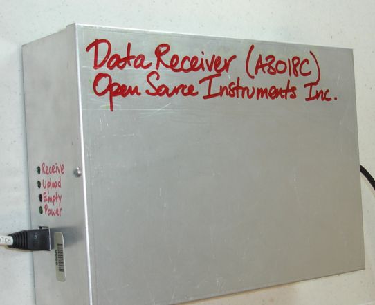
There are four indicator LEDs next to the RJ-45 socket. The green one closest to the socket is the power indicator (Power). The red LED shines when the message buffer is empty (Empty). The orange LED shines when the A3018 is uploading messages from the buffer to the LWDAQ driver (Upload). The far green LED shines when the A3018 is storing messages in the buffer (Receive).
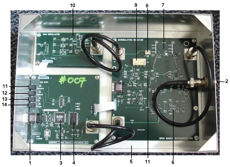
The A3018 combines three circuits, as shown in the picture above. The RF input passes to a Demodulating Receiver (A3017). The A3017 receives its local oscillator input from a SAW Oscillator (A3016SO). The demodulated output of the A3017 connects to a Data Recorder (A3007).
The following versions of the A3018 exist.
| Function Code |
Components | Comments |
|---|---|---|
| A | A3007C, A3016SO, A3017A | Original |
| B | A3007D, A3016SO, A3017A | Sensitive. |
| C | A3007D, A3016SO, A3017B | Rugged, sensitive. |
| D | A3007D, A3016SO, A3017C | Rugged, sensitive, low bad message rate. |
We corrected the A3018A to increase its sensitivity, and so produced the A3018B. We modified the RF Amplifier to make it more tolerant of component variation, and so created the A3018C. We discovered a bug in the firmware in 2013, fixed this bug, and so produced the A3018D.
We won't be making any more A3018s. Instead, we are making the Octal Data Receiver (A3027), which provides eight independent antenna inputs compared to the A3018's single antenna input. That's not to say that the A3018 is in any way faulty: with one antenna, it gives performance equal to the A3027 with one antenna. But once we plug two or more antennas into the A3027, spaced within 50 cm of the transmitter, the A3027 gives better performance (see measurements for transmitters in an RF isolation chamber).
In 2017 we introduced transmitter with channel numbers 17-255. The A3018 must be re-programmed with firmware FV=8 or later in order to receive signals from these higher channel numbers. The firmware version is displayed in the Receiver Instrument when you acquire data from the A3018.
Note: All our schematics and Gerber files are distributed for free under the GNU General Public License.
Code: Firmare for the data receiver logic.
S3017_1: RF Amplifier, Downshifter, IF Amplifier, and Discriminator sections of the Demodulating Receiver (A3017).
S3017_2: Demodulator and Power Supply sections of the Demodulating Receiver (A3017).
S3007_1: Demodulated Input, LWDAQ Connection, Programmable Logic, Reference Oscillator, and RAM sections of the Data Recorder (A3007).
S3007_2: Clock Oscillator, Power Distribution, and Indicator Lamp sections of the Data Recorder (A3007).
S3016_3: SAW Oscillator section of RF Combo (A3016).
LED Holes: LED Holes on Box Side
Plug the Data Receiver (A3018) into the LWDAQ. Wait a few seconds. Check that the power light is on. If not, reset the LWDAQ driver by unplugging its main power and plugging it in again. If your LWDAQ driver has firmware version FV=10 or higher, you can achieve the same power-cycle effect by pressing its hardware reset button.
Plug in an antenna. Turn on a transmitter. You should see the Receive light come on. Move the transmitter around. Interpose your body between it and the antenna. You should see the Receive light flicker every now and then as you hit a reception dead spot.
Turn on the LWDAQ, open the Receiver Instrument. Point the Receiver Instrument to the A3018 and press Acquire. You should see the transmitter trace on the screen. The A3018 stores 128 clock messages in its message buffer every second. Its clock tick frequency is 32.768 kHz.
See Subcutaneous Transmitter for more operating instructions.
The Local Oscillator provides the LO input to its Demodulating Receiver. The local oscillator is an A3016SO with a B3563 SAW Filter from Epcos in place of L100. The LO output is +9±1 dBm at 864±1 MHz. We use solder lumps in place of C100 and C104. The oscillator output power is +10 dBm when supplied with +5V, but when the power supply drops to 4.5 V, as it can do with long cables and multiplexers between the driver and the A3018, the oscillator output power can drop to +6 dBm. Even at +6 dBm, the power is sufficient to drive the mixer on the Demodulating Receiver.
We discuss the Demodulating Receiver in detail here. It consists of an antenna amplifier, a mixer, a limiting amplifier, and a demodulator. The antenna amplifier amplifies the antenna signal by 20 dB, passes the signal through a 902-928 MHz SAW filter, and amplifies the signal again. The mixer takes this 902-928 MHz signal and down-shifts it to 38-64 MHz using the 864 MHz LO signal provided by the Local Oscillator.
Note: Initial versions of the antenna amplifier used three 100-Ω resistors in series to bias the ERA-3SM amplifiers. The amplifier quiescent current was 40 mA. But the recommended operating point of the amplifiers is 35 mA. We found that some amplifiers were failed after a few days running, while others kept going indefinitely. We raised the bias resistance to 350 Ω, giving us a 34 mA current, and no amplifiers failed after two weeks running.
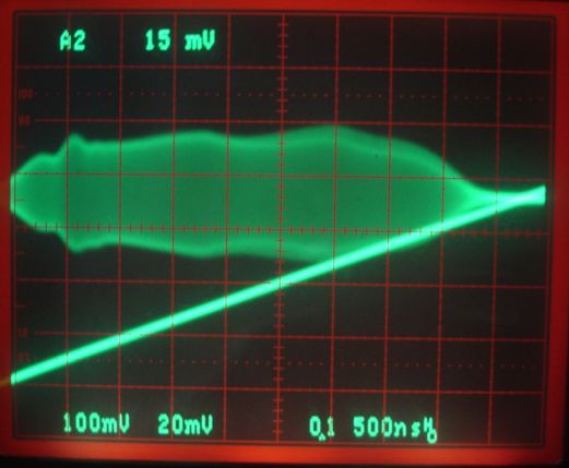
The gain from the antenna input to the IF output from the mixer should be +29 dB at the center of the SAW filter pass-band. You will find a trace of the IF output with a sweeping RF input here.
The limiting amplifier takes the IF signal from the mixer and amplifies it by up to 60 dB until it saturates.
Note: Initial versions of the limiting amplifier used 1-nF decoupling capacitors on the power supplies to the limiting op-amps. With 10-nF decoupling capacitors, the noise at the output of the first stage of the limiting amplifier decreased by 10 dB. We changed the schematic and modified existing circuits so they used 10-nF capacitors.
The demodulator takes the limited IF signal and passes it through a resonant circuit and then a full-wave rectifier. The resonant circuit is a resistor, capacitor, and inductor.
The Data Recorder (A3007) takes the output of the Demodulating Receiver, passes it through a discriminator filter, converts it into logic levels with a comparater, and looks for transmitter messages in the resulting bit sequence. We describe messages detection in the Signal Path section of Subcutaneous Transmitters. The Data Recorder provides four indicator lights: Power, Empty, Upload, and Receive.
The A3018A uses the A3007C Data Recorder, while the A3018B uses the A3007D Data Recorder. The A3007D provides superior performance for weak signals by means of a superior discriminator filter. The discriminator filter consists of R2, C4, R3, and C8, followed by U5 (see schematic). The frequency response of this network, from the D to U5-3, is shown below, for both the A3007C and A3007D.
The SCT messages are 5-MHz square waves. The shortest HI or LO is 100 ns. The longest HI or LO is 200 ns. Most of the power of the signal lies within the range 2 MHz to 20 MHz. The A3007D discriminator picks out this frequency band and provides better detection of weak signals than the A3007C. The A3007C performed a simple high-pass filter function, which gave signals that looked better to the human eye on the oscilloscope. When we move a transmitter randomly inside a Faraday Enclosure, we obtain 98% reception with the A3007D, but only 92% reception with the A3007C.
The Demodulating Receiver schematic shows a 0-Ω resistor in series with its output (R222). But some versions of the A3017 included a 50-Ω output resistor by mistake, and this resistor interacts with the A3007D's discriminator circuit so as to alter its frequency response. The figure above shows how the peak of the response moves down from 4.5 MHz to 2.5 MHz. We see no significant change in detection of weak signals as a result of this mistake, but we do observe an increase in the number of bad messages received within a faraday enclosure. In one experiment, the bad message rate decreased from 3/s to 0.5/s when we removed the 50-Ω resistor. In another, it decreased from 30/s to 4/s. Thus we prefer to remove R222 and replace it with a solder lump when we discover the mistake.
The A3007D Receive indicator behaves slightly differently from that of the earlier A3007C. The A3007D's indicator flashes for only 2 ms after receipt of a message, while the A3007C's flashes for 20 ms. The A3007D indicator reaches full intensity only when it is receiving at least 500 messages per second. For less frequent reception, the indicator will be proportionately dimmer. The A3007C's indicator does not start to dim unless there have been no messages received for 20 ms.
The Power indicator shines if the board's logic power supply is on. Sometimes, when we plut the A3018 into the LWDAQ, the Power indicator does not come on. Plug it in again, or press the reset button on the front of the LWDAQ Driver. The Power light should now turn on.
The Upload indicator flashes when the A3018 is uploading messages to the LWDAQ Driver. The Empty indicator turns on when the message buffer is empty. During continuous data acquisition, we should see the Empty indicator turning on at the end of every message upload. So we should see the Upload indicator turn on, then the Empty indicator, then both will turn off together at the end of the upload.
[17-MAY-13] We discover a severe bug in the A3007 firmware, which has been present since 2007. We correct this bug and the A3018's immunity to interference increases a hundred-fold. We can now operate the A3018 with an A3008 spectrometer with no problems. The A3018D will be the first version of the A3018 with the new firmware.
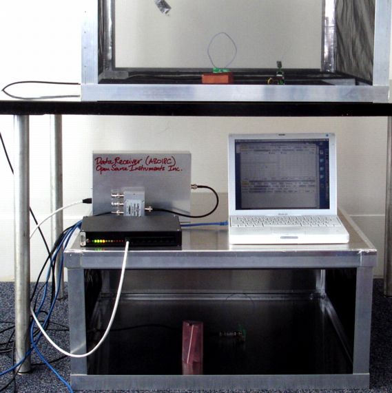
The cable that connects the A3018 to its LWDAQ Driver will act like a radio-frequency antenna unless it has a good high-frequency shield. This shield is grounded at the A3018 enclosure. To demonstrate the effect of shielding, we performed the following experiment. We worked with this sytem, where two faraday enclosures are connected through an antenna combiner to an A3018C. The antennas are A3015As with 3-dB attenuators added to them. In the FE2A enclosure is transmitter No7. In the FE2B enclosure is transmitter No9. We recorded reception and the bad message rate as we alternated between a a 1-m stranded-wire, shielded, LWDAQ Cable and a 1-m stranded-wire, unshielded ethernet cable. The following graph presents our measurements.
By switching from shielded to unshielded we see repeatedly a dramatic drop in reception from one of the transmitters, and a simultaneous jump in the bad message rate. We recorded this data in the morning in our OSI office in the center of Waltham, MA.
The above experiment is closely related to our experiments with attenuators and antennas.
If we rub our feet on the carpet and touch a faraday enclosure, we will get a spark. Current flows through the cage, along the coaxial cable, to the A3018. Unless we ground the enclosure of the A3018, this current has nowhere to go except along the cable to the LWDAQ Driver. The static discharge current must pass along the power supply wires within the cable. There is no direct-current path through the cable shield. The surge of current induces a voltage difference between the A3018 and the LWDAQ Driver, which can cause a false logic LO to be received by the LWDAQ Driver from the A3018 during data download. This false low will cause an extra byte to be inserted into the data. This byte will almost always have value 255 (hex FF).
In LWDAQ 7.5.1 we added error-correction to the Receiver Instrument. The error-correction finds and removes extra bytes in the acquired data. Almost all static discharge events will now be handled gracefully.
Static discharge causes far more disruption when we use an unshielded cable from the A3018 to the LWDAQ Driver. With a shielded cable, only one out of ten discharges causes data corruption. Without a shield, almost every discharge causes corruption.
We measured the current consumed by three A3018As, and found them to be within a few milliamps of one another on all three power supply voltages.
| −15 V | +5 V | +15 V |
|---|---|---|
| 72 mA | 166 mA | 107 mA |
The A3018C uses +5V for the RF amplifier, and so consumes less current from +15V and more from +5V.
| −15 V | +5 V | +15 V |
|---|---|---|
| 70 mA | 240 mA | 40 mA |
The bad message rate increases with interference. With −68 dBm interference and no faraday enclosure, we get an average of 1.1 bad messages per second with standard deviation 2.5. In most seconds we get no bad messages, and in some we get 15.
We report further upon bad message rates in the Loop Antenna (A3015A) manual and the Shielding section above.
The A3018B and A3018C firmware in the interior A3007 circuit had a bug in it that increased the bad message rate in the presence of interference by a factor of one hundred. We fixed this bug in May 2013, and the upgraded A3018Cs we named A3018Ds.
[14-MAR-18] We receive back from UCL A3018D Q0128. Half the base screws are missing. Re-assemble. Program with FV=8. We receive back from Aston A3018D P0230. No screws missing. Reprogram with FV=8.