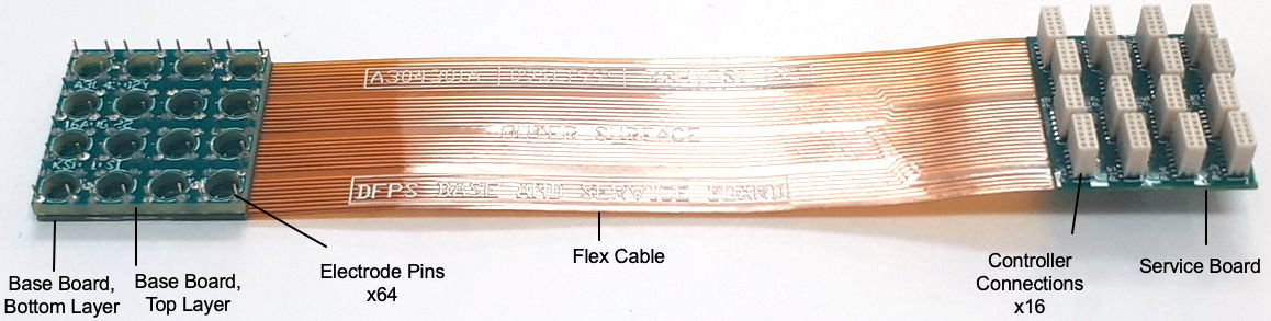
[11-JUN-24] The Direct Fiber Positioning System (DFPS) Base and Service Board (A3043) consists of a base board that holds sixteen fiber positioners and a service board that provides sixteen connectors for fiber controllers. The two boards are joined by a flex cable that carries sixty-four electrode voltages for the sixteen positioners. Sixteen DFPS Fiber Controllers (A3045A) plug into one side of the service board. On the other side is a ten-way connector that plugs into a DFPS Backplane (A3044A).
The base board and service board are roughly 19 mm square. They must fit inside a 20-mm square envelope so that we can maintain a 5-mm × 5-mm density of fibers. The A3043B places the sixteen actuators on a 4.6-mm grid so as to make space around the perimeter for four mounting pins. The A3043B connects to an A3044CS cell support by means of these four pins. The sixteen connectors for the fiber controllers are packed onto the service board in a staggered arrangement that allows all sixteen fiber controllers to fit into the 19-mm square.

The actuators of the positioners load into the counter-boarded holes of the base board. We use a drop of epoxy to fasten each actuator in place. We align the actuator electrodes with the footprints on the board, hoping to get all of them aligned to within a few degrees. Once the epoxy is cured, we solder the four electrodes, sometimes with the help of a narrow, bent, flat-tipped soldering bit. Each of these electrode connections passes along the flex cable to the service board. The tracks carrying these potentials are 5 mil wide (125 μm). They alternate from top to bottom layer on the flex cable. Their pitch is 10 mils (250 μm). We must not run the tracks opposite one another on the flex cable, or else they are likely to short to one another where we bend the flex cable sharply where it emerges and enters the rigid sections. With this spacing, we are approaching the highest density we can achieve with a flex cable and still have adequate insulation between ±250 V signals.
The following versions of the DFPS Base and Service Board (A3043) exist.
| Version | Actuator | Geometry | Controller | Comment |
|---|---|---|---|---|
| A3043A | 3.6-mm OD | 4 × 4 on 5-mm grid | A3045A | For sixteen-fiber cells. |
| A3043B | 3.6-mm OD | 4 × 4 on 4.6-mm grid | A3045A | For sixteen-fiber cells. |
[29-JUL-24] Design files for the A3043 base and service board, various versions and auxiliary boards.
A304301B.zip: Base and Service Board PCB Version B.
[08-JUN-22] Draft layouts of top and bottom layer 61-mil thick circuit boards that we will glue together to form the 125-mil thick base board with counter-sinks for the positioner end caps.
[23-JUN-22] Our A304301X board looks good, see photo below. Our A304302XR1 has a problem: our Gerber files included a copper annulus around the actuator holes, which will short the electrodes. We prepare A304302XR2 with no copper around the actuator holes top or bottom, and no solder mask clearance on the top side.
[15-AUG-22] We are trying to devise a way to assemble the two layers of the base board, allowing for the top layer to be rigid only, the bottom layer to be rigid-flex, in which the top and bottom layers are well-aligned with pins, the actuators are provided with protruding pins for their electrode contacts, the electrode connections are made through the caps of these actuator pins being surface-mount (SMT) soldered in our SMT reflow oven, and we glue the sixteen positioners into the base board at the same time we glue the base board to the base plate in our assembly jig.
After soldering all the actuator pins to the top side of the top layer, we apply solder paste to the caps of these pins, fasten the bottom layer to the top layer with four pins that we hand-solder to the top side of the top layer and the bottom side of the bottom layer, then place in the reflow oven to get the actuator pin heads to weld to the pads on the top side of the bottom layer. One concern is the distance between the flange of the ferrule that will mount in the top layer hole.
Another concern is our ability to solder the actuator pins to the electrodes of the actuators in the center of the 4 × 4 array. One plan is to hand-solder with a soldering tip that is less than 1.4 mm wide. Another is to apply solder paste to all the pins with a syringe tip 1-mm in diameter, then place in the reflow oven. In both cases, we remove the entire positioner cell from our assembly jig, so that we have the base plate, base baord, and its sixteen positioners glued together. We place on our work surface and rotate to give ourselves access from all sides.
[16-AUG-22] We submit A304301Y and A304302Y for fabrication, width 0.8 and 1.6 mm respectively, with CNC machining for the borders.
[25-AUG-22] We receive A304301Y and A304302Y. We assemble with the sixteen electrode pins and four fiducial pins. Alignment of the ferrule and flange holes appears perfect. We are able to solder positioners to the pins easily. We did not add paste to the electrode pin heads. Next time, we will add the paste before joining the two boards, place in oven, and see if we can get all sixty-four pins to weld to the pads on the lower layer.
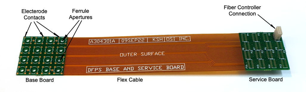
[09-SEP-22] Base and Service Board rigid-flex PCB A304301A layout is done. We are checking the netlist. The board is six layers with 4-mil tracks, 5-mil spacing, and a two-layer central flex portion that joins the base and service sections. Circuit diagram is A3043A_1.gif.
[05-OCT-22] We have our A304301A, see here. We load P1 and P17. We believe we can load all connectors by hand.
[07-OCT-22] We rip off P17 by accident, pulling off a fiber controller. We load two other connectors and insert two fiber controllers. We observe eight ramping electrode voltages on the pads on the base board, carried there by the flex cable. We apply black potting epoxy to the base of the controller connectors, in the hope that this will secure them better.
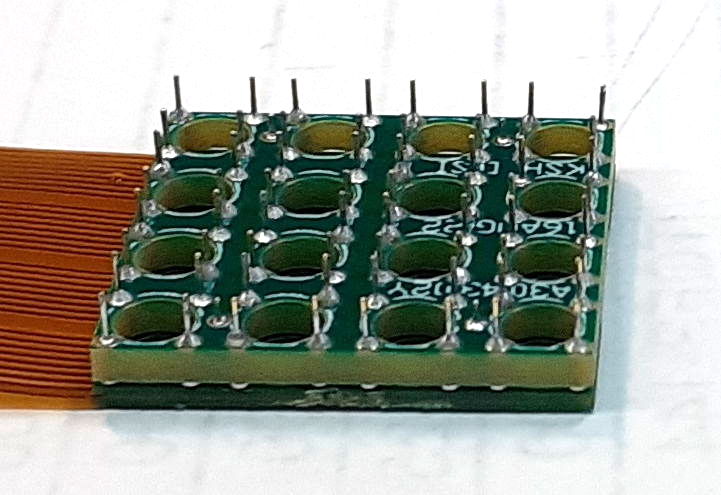
[19-OCT-22] We assemble a complete sixteen-positioner base board with the help of the reflow oven. We check all connections between the electrode pins and the contacts on the service board connector footprints. We check for contact between neighboring electrodes. We have no short circuits. We have no open circuits. For photograph of pin array here.
[26-OCT-22] We load sixteen controller connectors by hand with the help of a new narrow-shaft soldering bit. We connect two fiber controllers programmed to generate ramps with their amplifiers, power up with 500 V and observe the ramps on our pins. For photograph of connectors see here. The positioning of the connectors is accurate to ±0.2 mm, which is good enough for the controllers to fit.
[21-DEC-22] The base and service board plugs into a Backplane (A3044) for the first time, mating with its 0.050" header, and all connections are correct.
[01-FEB-23] We are loading fiber controllers onto our service board, shown below. Connector P12 we ripped off a while back. We secured the rest of the connectors in place with black epoxy. But now we find that five of the remaining fifteen controller plugs are missing their 0V connection.
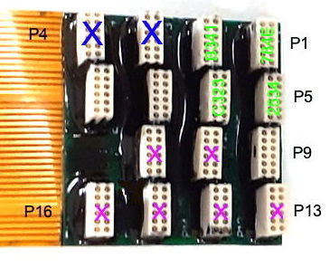
We plug a controller into each of the fifteen plugs in turn. We look for a DAC square wave on the controller and we check for connection between the controller's 0V pad and our command transmitter 0V. We see a DAC square wave if and only if we have 0V connection. Otherwise we see 1.2 V on each DAC output with no 0V connection. Looking at the connector layout, we suspect that the track marked below is broken.
Damage to the track may have occurred when we ripped the P12 plug off the board. The track supplying 0V to all five faulty plugs may have ripped off the 0V next to P9. We now try the fiber controller in each of the working sockets, applying ±250V and watching for movement of the masts. Of the nine good connectors, we see movement in eight masts. The mast that does not move is the one connected to P4. The fiber controller is producing all electrode voltages, but none of them are appearing on the actuator. We check three of the actuator's electrode pins and find 0 V on all three. We suspect that the pin heads are not soldered to the base board. We see roughly 254 μm of movement in one fiber, while 15 mm separation of masts appears as 950 μm on the image sensor. The mast tips is moving roughly 4 mm. A few of the fibers move the full 4 mm. Some move diagonally in our field of view, which suggests that one or more of their electrode potentials are missing. We repair A123 by replacing F1, U1 and U2. We program with ID E542. We load onto our service board and see movement of its fiber.
[08-FEB-23] Only seven of our sixteen actuators are able to move, thanks to damage to the service board and base boards.
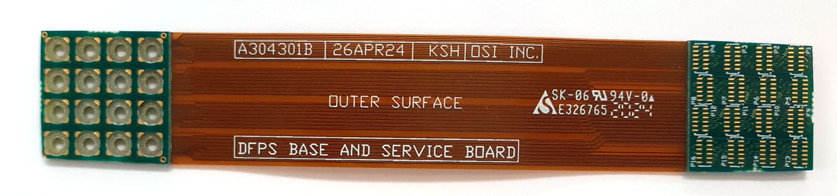
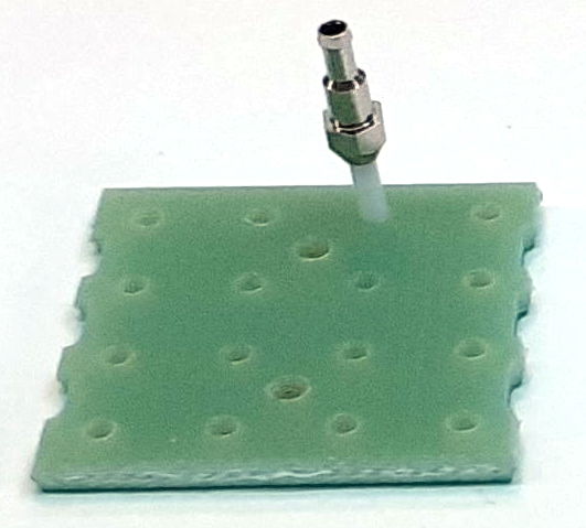
[26-APR-24] Our new Base and Service Board is the A304301B. We no longer need the mounting top-layer board that receives electrode voltages through pins. We mount the actuators in a counter-bore drilled into a 1.8-mm non-plated through hole. The counter-bore cuts through the electrode pads so that our pads come right up to the edge of the hole, where they may be soldered to the actuator.
The actuators themselves are on a 4.6-mm pitch, leaving space around the outsides for the four pins we use to fasten this board to the bridge. The bridge itself will be a PCB with rectangular cut-outs for all the fibers to run out the bottom of the 1.8-mm holes. The fibers will have ferrules at the top of the mast, but at the bottom they run out as continuous fibers to their injectors or the enclosure wall feedthrough connector.
[30-APR-24] Submit A304301B for fabrication on 15-day turn. We order 20 boards for $3300. The boards will come with counter-bores for the actuators to sit in. The counter-bores added only $300 to the order.
[13-MAY-24] In order to make our A304301B board, the fab house has to ensure 0.6 mm from edge of vias to edge of flex. So we ask them to extend the base board by 0.2 mm and they move several vias on the service board. Because of these changes, however, our A304301B PCB and Gerber files are no longer an exact match to the circuit board we are going to receive.
[24-MAY-24] We have the A304301B boards in hand. The counter-bore is perfect. We are able to sit four actuators in their counter-bores and solder them all in place within about thirty minutes, including the time it took us to make a new narrow-shaft soldering bit.